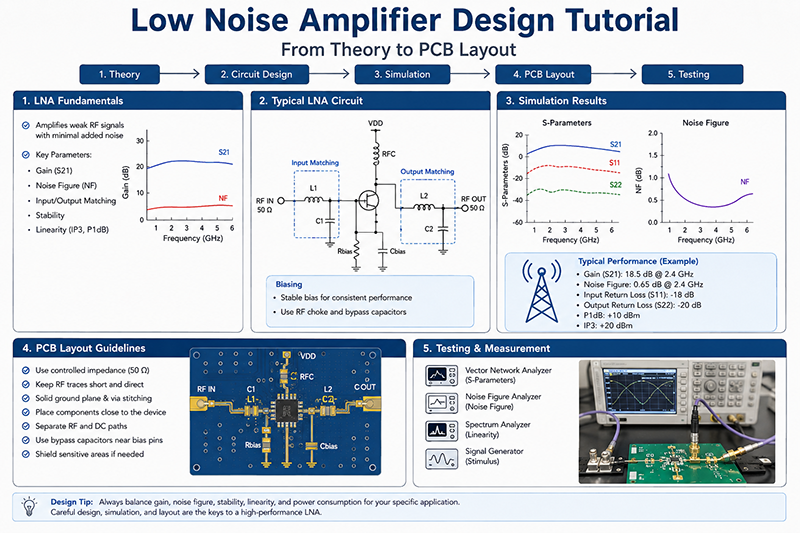
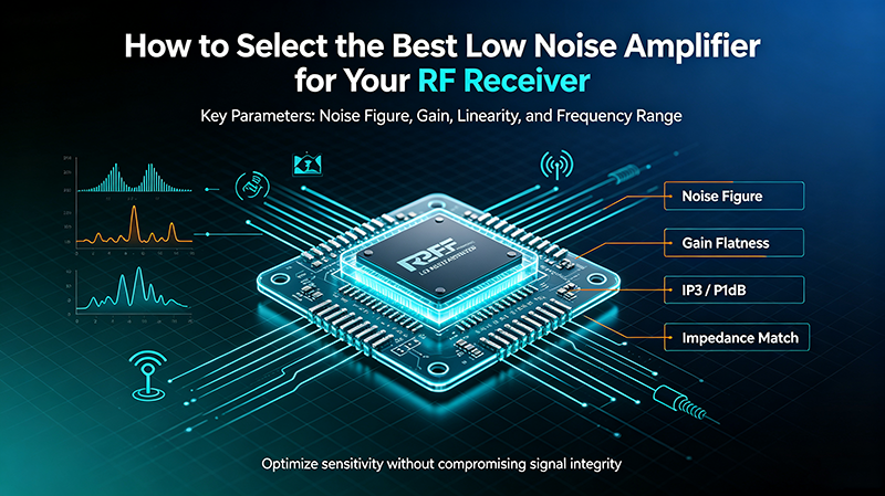
Radio Frequency Low Noise Amplifiers (LNAs) are critical components in modern wireless communication systems, serving as the first active gain stage in receivers and determining overall system sensitivity. From satellite communications to 5G base stations, automotive radar to IoT devices, LNAs enable the detection of weak signals in noisy environments. This comprehensive guide explores LNA technology, specifications, applications, and design considerations for 2026 and beyond.
What is a Radio Frequency Low Noise Amplifier?
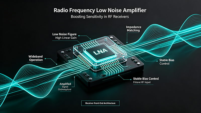
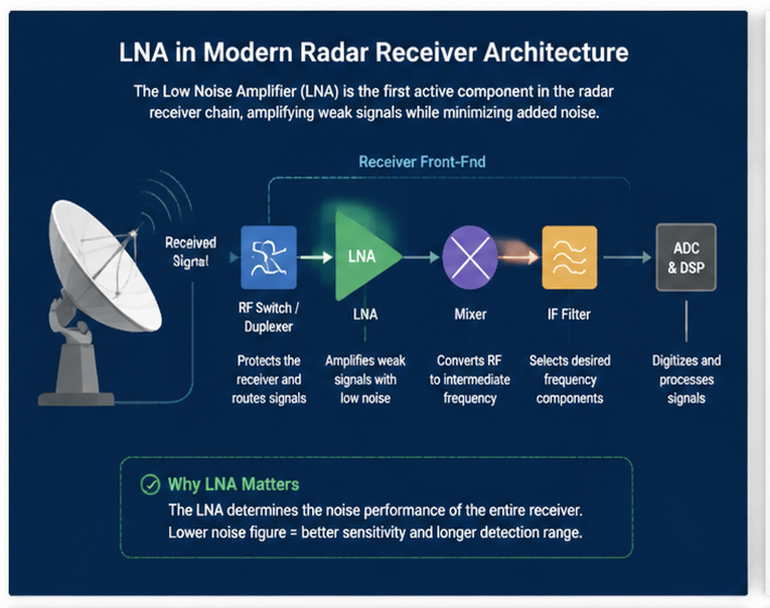
A Radio Frequency Low Noise Amplifier (LNA) is a specialized electronic amplifier designed to amplify very weak RF signals while introducing minimal additional noise. LNAs are typically placed at the front end of communication receivers, immediately after the antenna, where they must boost signal strength without degrading the signal-to-noise ratio.
The performance of an LNA directly determines receiver sensitivity. Because the LNA is the first active gain stage, any noise it adds cannot be removed by subsequent amplification stages. This makes LNA selection one of the most critical decisions in RF system design.
Why LNAs Are Essential
- System Sensitivity: LNA noise figure dominates system noise performance
- Signal Recovery: Boosts weak signals above receiver noise floor
- Cascade Performance: Reduces impact of subsequent stage noise
- Dynamic Range: Enables detection of small signals in presence of large interferers
- Modern Applications: Critical for 5G, satellite, radar, and IoT systems
Sensitivity (dBm) = -174 + 10*log10(BW) + NF + SNR_min
Key LNA Specifications Explained
Understanding LNA specifications is essential for selecting the right component for your application. Here are the most important parameters that define LNA performance.
Noise Figure (NF)
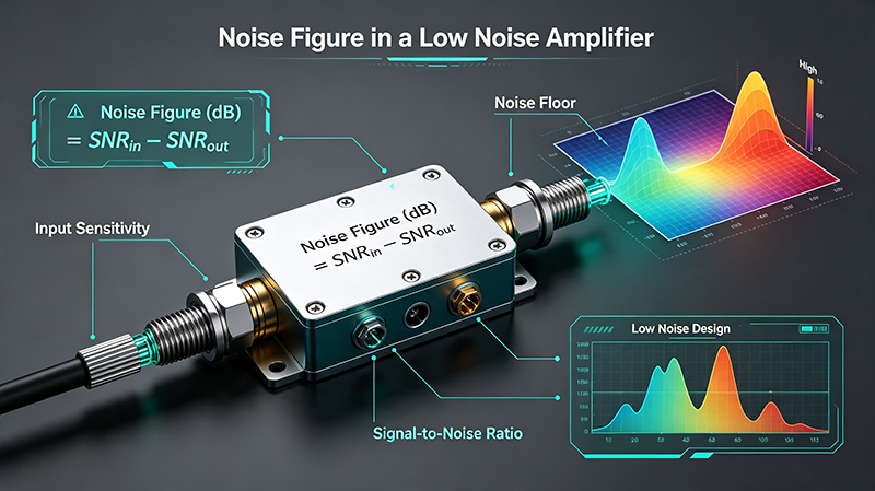
Noise Figure is the primary figure of merit for LNAs, measuring the noise added by the amplifier relative to the input noise. Lower NF means better sensitivity.
NF (dB) = 10*log10(SNR_input / SNR_output)
Gain
LNA gain determines how much the amplifier boosts the input signal. Higher gain reduces the impact of noise from subsequent stages, but excessive gain can cause compression and intermodulation issues.
Linearity (IP3, P1dB)
Linearity specifications define how the LNA handles large signals without distortion. Critical for systems with strong interferers or high-order modulation schemes.
IIP3 = Input power + (Output IM3 power - Input power) / 2
Frequency Range
The operating frequency band over which the LNA maintains acceptable performance. Modern LNAs cover from VHF through millimeter-wave frequencies above 100 GHz.
VSWR and Matching
Voltage Standing Wave Ratio measures impedance matching quality. Better VSWR means less signal reflection and improved power transfer from the antenna.
| Specification | Typical Range | Impact |
|---|---|---|
| Noise Figure | 0.3 - 3 dB | Determines sensitivity |
| Gain | 10 - 40 dB | Signal amplification |
| IP3 | +5 to +30 dBm | Linearity performance |
| P1dB | -10 to +15 dBm | Compression point |
| VSWR | 1.3:1 - 2.0:1 | Impedance match |
| Frequency Range | DC to 100+ GHz | Operating bandwidth |
| Power Consumption | 10 - 500 mW | Battery life |
Specification Trade-offs
LNA design involves balancing multiple parameters that often conflict. Lower noise figure typically requires higher current consumption. Higher gain can improve noise figure but reduces linearity. Higher linearity enables better handling of interferers but may degrade noise figure. Understanding these trade-offs is key to optimal LNA selection.
LNA Technologies and Materials
Different semiconductor technologies offer distinct advantages for LNA design. Selecting the right technology is crucial for meeting application requirements.
GaAs pHEMT Technology
Gallium Arsenide pseudomorphic High Electron Mobility Transistors are the industry standard for high-performance LNAs. They offer excellent noise figure, good gain, and high frequency operation up to 50 GHz.
InP HEMT Technology
Indium Phosphide HEMTs provide the lowest noise figures available, with values below 0.5 dB at microwave frequencies. Used in premium applications where performance is paramount.
GaN HEMT Technology
Gallium Nitride HEMTs offer superior linearity and power handling, making them ideal for 5G infrastructure where high-order modulation creates demanding linearity requirements.
SiGe BiCMOS
Silicon Germanium technology provides good noise performance with the integration benefits of silicon processes. Excellent for cost-sensitive applications and integrated solutions.
CMOS Technology
Modern CMOS processes offer LNAs with adequate performance for many applications at the lowest cost. Ideal for high-volume consumer applications and IoT devices.
GaAs pHEMT
NF: 0.5-1.5 dB
Frequency: DC-50 GHz
Best For: Premium LNAs
InP HEMT
NF: 0.3-0.8 dB
Frequency: DC-100 GHz
Best For: Lowest noise
GaN HEMT
NF: 1.0-2.0 dB
Frequency: DC-40 GHz
Best For: High linearity
SiGe BiCMOS
NF: 1.0-2.5 dB
Frequency: DC-30 GHz
Best For: Integrated solutions
CMOS
NF: 1.5-4 dB
Frequency: DC-20 GHz
Best For: Low cost
Design Considerations
Successful LNA design requires careful attention to multiple factors affecting performance, reliability, and manufacturability.
Input Matching
Optimal LNA input matching often differs from 50 ohms. The minimum noise figure is achieved at a specific source impedance that may not be 50 ohms. Designers must balance minimum NF against input VSWR requirements.
Stability
LNA stability is critical. The amplifier must remain stable across all operating conditions, including temperature variations, bias changes, and source/load impedance variations.
K = (1 - |S11|^2 - |S22|^2 + |D|^2) / (2|S12*S21|)
Bias Optimization
Bias current affects noise figure, gain, linearity, and power consumption. For GaAs and InP devices, minimum NF typically occurs at 10-30% of Idss, not the maximum rated current.
Thermal Management
LNA performance degrades with temperature. Noise figure increases approximately 0.01-0.02 dB per degree Celsius above 25°C. Proper thermal design is essential for stable operation.
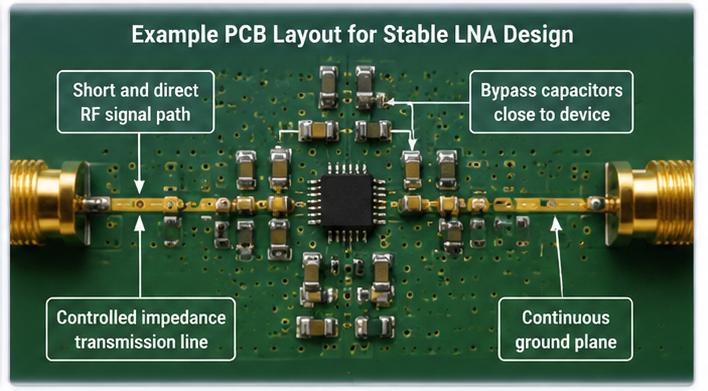
Layout and Packaging
At high frequencies, package parasitics significantly affect performance. Bond wire inductance, package capacitance, and PCB trace effects must be carefully controlled for optimal results.
Protection
LNAs are sensitive to ESD and overdrive conditions. Proper input protection circuits are essential for field reliability, especially in base station applications.
Common Applications
5G Base Stations
5G massive MIMO base stations use 64-128 LNAs per antenna array. LNA noise figure directly determines cell coverage and capacity in modern wireless networks.
Satellite Communications
Satellite ground stations and user terminals require extremely low noise figures to detect weak signals from orbit. Premium InP LNAs are often used with cryogenic cooling for ultimate performance.
Radar Systems
Military and weather radars use LNAs to maximize detection range. GaN LNAs provide excellent linearity for handling strong clutter and interference.
GPS/GNSS Receivers
GPS LNAs with sub-1 dB noise figure are essential for navigation, timing, and positioning applications. Specialized LNAs amplify weak satellite signals while adding minimal noise.
Automotive Radar
77/79 GHz automotive radar uses LNAs optimized for mmWave frequencies. AEC-Q100 qualified LNAs ensure reliability in harsh automotive environments.
Electronic Warfare
EW systems use LNAs to detect and analyze weak enemy signals. Wideband LNAs enable coverage of multiple threat frequency bands.
Test Equipment
Network analyzers, spectrum analyzers, and other test equipment use LNAs to improve sensitivity for measuring weak signals.
IoT Devices
Low-power LNAs enable wireless connectivity in battery-powered IoT devices, balancing performance with energy efficiency.
LNA Selection Guide
Follow these steps to select the optimal LNA for your specific application requirements.
Step 1: Define Requirements
- Operating frequency range
- Maximum acceptable noise figure
- Required gain
- Linearity requirements (IP3)
- Power consumption constraints
- Size and package requirements
- Environmental conditions
Step 2: Calculate System NF Budget
Use the Friis cascade formula to determine what LNA NF your system requires:
NF_total = NF1 + (NF2-1)/G1 + (NF3-1)/(G1*G2) + ...
Step 3: Choose Technology
Select semiconductor technology based on frequency, noise figure, linearity, and cost requirements. Compare GaAs, InP, GaN, SiGe, and CMOS options.
Step 4: Evaluate Candidates
Compare multiple LNA options against your requirements. Request samples for evaluation before committing to production orders.
2026 Industry Trends
The LNA market continues to evolve rapidly, driven by 5G expansion, emerging 6G research, and new application requirements. Key trends include:
- GaN LNA Adoption: Increasing use in 5G base stations for superior linearity with 256-QAM and 1024-QAM modulation
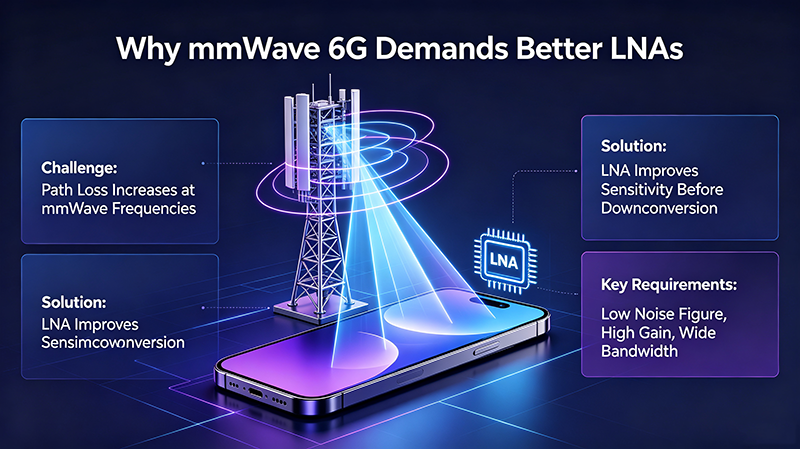
- mmWave Expansion: Growing demand for 24-40 GHz and higher frequency LNAs for 5G FR2 and emerging applications
- Integrated Modules: LNAs with integrated filtering, switching, and bias control in single packages
- AI-Optimized Designs: Machine learning tools for LNA design optimization
- Energy Efficiency: Lower power consumption for sustainable wireless infrastructure
- 6G Research: Development of LNAs for sub-THz frequencies (140-300 GHz)
- Software-Defined LNAs: Digitally controlled LNAs with programmable gain and bias
- Automotive Growth: 77/79 GHz automotive radar LNAs with enhanced reliability
Future Outlook
The RF LNA market will continue strong growth driven by global 5G deployment, satellite constellation expansion, automotive radar adoption, and emerging applications. Technologies like GaN, integrated modules, and AI-optimized designs will shape the industry's future.
Frequently Asked Questions
Conclusion
Radio Frequency Low Noise Amplifiers are fundamental components that determine the sensitivity and performance of modern wireless systems. From 5G base stations to satellite communications, from automotive radar to IoT devices, LNAs enable the detection of weak signals in increasingly challenging RF environments.
Understanding the fundamental parameters, technology options, and application requirements enables engineers to make informed LNA selection decisions. The optimal LNA balances noise figure, gain, linearity, power consumption, and cost for specific system requirements.
As wireless systems continue to evolve with 5G expansion, emerging 6G research, and new application requirements, the LNA market will continue growing. Technologies like GaN, integrated modules, and AI-optimized designs will lead the industry's future, providing even better performance for next-generation wireless systems.
Looking for the Right LNA for Your Application?
Our engineering team can help you select the optimal RF low noise amplifier for your specific requirements. Contact us for expert guidance and technical support.
Contact Our Technical Team