


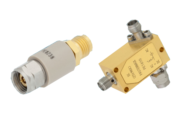
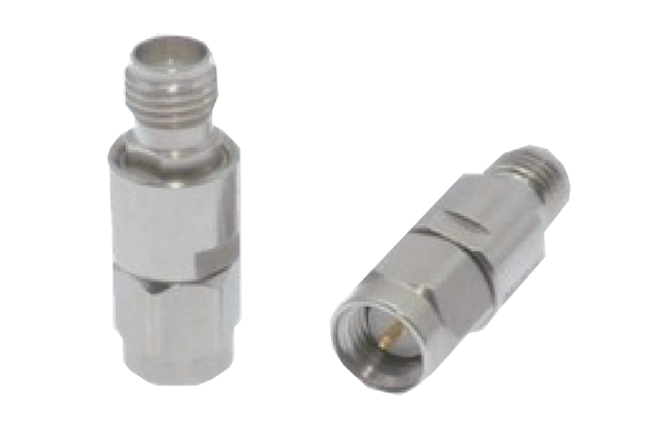
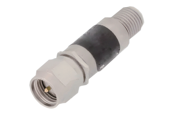
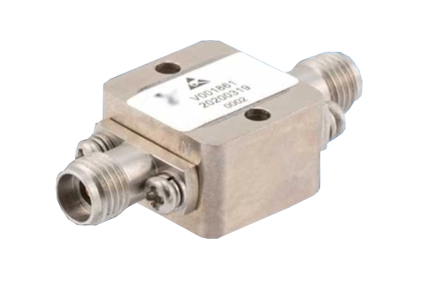




In modern RF and microwave systems, controlling signal direction and preventing unwanted reflections are essential for maintaining system stability and performance. Two important passive components used for this purpose are RF isolators and RF circulators. Although they share similar ferrite-based operating principles, their functions, port configurations, and applications are different.
Understanding the differences between an RF isolator and a circulator helps RF engineers select the right component for applications such as wireless communications, radar systems, satellite communications, microwave testing, and high-power RF transmission.
1. What Is an RF Isolator?
An RF isolator is a passive, non-reciprocal microwave component designed to allow electromagnetic signals to pass in one direction while providing high attenuation in the opposite direction.
Its primary function is to protect sensitive RF equipment from reflected signals caused by impedance mismatches, antenna reflections, or changes in load conditions.
For example, when an RF power amplifier drives an antenna, a portion of the transmitted signal may be reflected because of an impedance mismatch. These reflected signals can travel back toward the amplifier and potentially cause performance degradation, instability, or damage.
An RF isolator reduces this risk by directing reverse-traveling energy toward an internal matched termination rather than allowing it to return to the source.
How Does an RF Isolator Work?
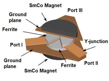
Most conventional RF isolators use magnetically biased ferrite materials to create non-reciprocal electromagnetic behavior. Unlike reciprocal components, such as ordinary attenuators and filters, a ferrite isolator exhibits different transmission characteristics depending on the direction of signal propagation.
A typical ferrite isolator consists of:
- Ferrite material: Provides the non-reciprocal microwave interaction.
- Permanent magnet: Establishes the required magnetic bias field.
- Microwave transmission structure: Guides RF energy through the device.
- Impedance-matched termination: Absorbs reverse-traveling signals.
- RF connectors or waveguide interfaces: Provide input and output connections.
Forward transmission: Low insertion loss
Reverse transmission: Reflected energy is absorbed by the termination
Key Performance Parameters of an RF Isolator
| Parameter | Definition | Engineering Importance |
|---|---|---|
| Insertion Loss | Signal power lost during forward transmission | Determines forward signal efficiency |
| Isolation | Attenuation of signals traveling in the reverse direction | Indicates protection against reflected signals |
| Return Loss | Measure of input or output impedance matching | Affects reflections and VSWR |
| VSWR | Voltage Standing Wave Ratio | Indicates impedance matching quality |
| Power Handling | Maximum permissible RF power | Ensures safe operation under specified conditions |
| Operating Frequency | Frequency range over which specifications are maintained | Determines compatibility with the RF system |
2. What Is an RF Circulator?
An RF circulator is a passive, non-reciprocal microwave device that directs signals sequentially from one port to the next in a predefined direction.
Unlike an isolator, which primarily provides one-way transmission between two ports, a circulator can route signals among multiple ports without requiring an internal termination at every port.
Most RF circulators have three or four ports. A three-port circulator typically routes signals in the following sequence:
- Port 1 to Port 2
- Port 2 to Port 3
- Port 3 to Port 1
Reverse-direction transmission is strongly attenuated, depending on the component's isolation specification.
How Does an RF Circulator Work?
Ferrite-based RF circulators operate through the interaction between electromagnetic waves and magnetically biased ferrite materials. The magnetic bias produces non-reciprocal phase characteristics that enable directional signal routing.
The internal electromagnetic field distribution is designed so that energy entering one port preferentially exits through the next designated port.
The signal continues from Port 3 back to Port 1, completing the circulation path.
Common Types of RF Circulators
Three-Port Circulator
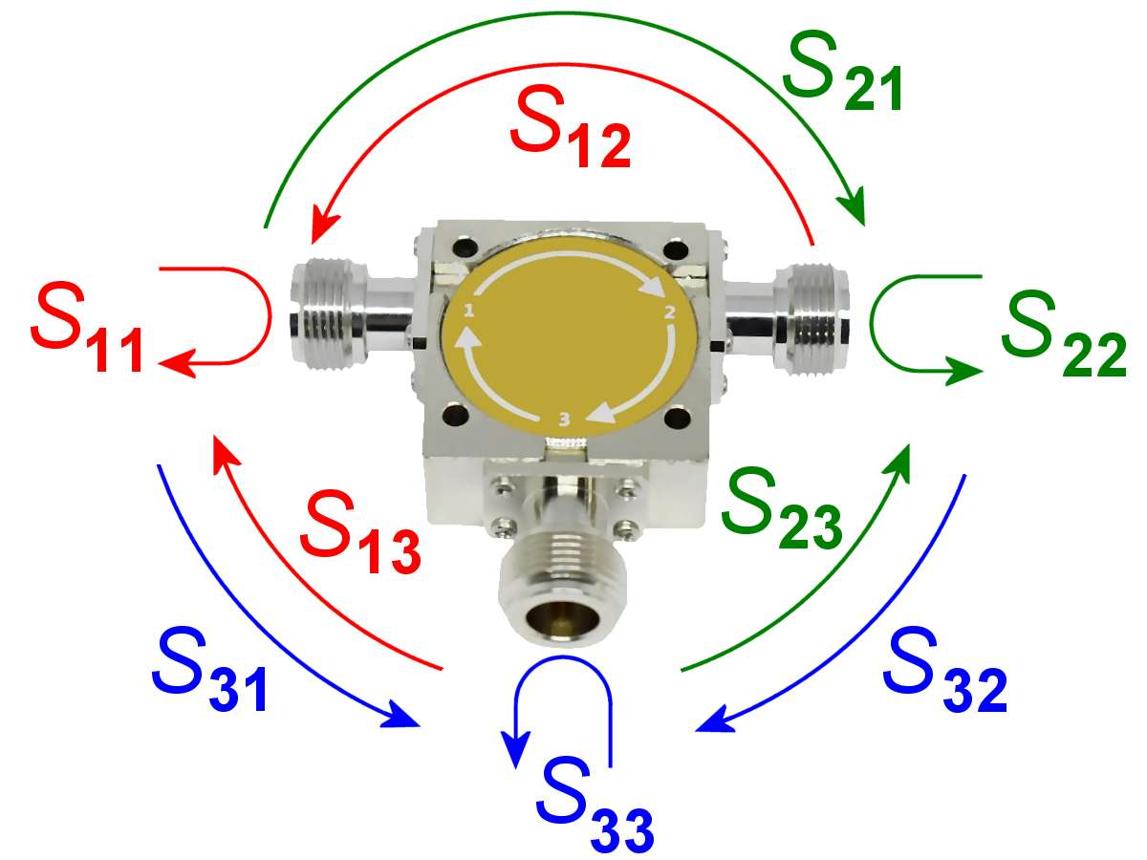
A three-port circulator is widely used in RF transmission and reception systems. It can separate transmitted and received signals when connected to an antenna.
For example, in a radar or wireless communication system, the transmitter signal can travel from Port 1 to Port 2, while a received signal entering Port 2 can be routed from Port 2 to Port 3.
Four-Port Circulator
A four-port circulator routes signals sequentially through four ports. Its directional routing capability makes it useful in more complex microwave signal distribution, measurement, and communication systems.
The typical routing sequence is:
- Port 1 → Port 2
- Port 2 → Port 3
- Port 3 → Port 4
- Port 4 → Port 1
3. RF Isolator vs. Circulator: Key Differences
Although RF isolators and circulators use similar non-reciprocal ferrite technology, they serve different purposes in microwave systems. The most important distinction is that an isolator provides directional protection, whereas a circulator provides directional signal routing.
| Comparison | RF Isolator | RF Circulator |
|---|---|---|
| Primary Function | Protects RF sources from reflected power | Routes signals between multiple ports |
| Typical Ports | 2 ports | 3 or 4 ports |
| Signal Direction | Forward transmission with reverse isolation | Sequential directional signal routing |
| Internal Termination | Usually includes a matched load | Normally does not require an internal termination at every port |
| Reverse Signal Handling | Absorbs reverse energy in its termination | Routes reverse-entering energy to the preceding port |
| Typical Application | Amplifier protection and impedance mismatch isolation | Transmitter-receiver signal separation |
| System Configuration | Two-port connection | Multiple-port connection |
| Design Consideration | Isolation, insertion loss, and power dissipation | Isolation, insertion loss, and port matching |
Is an RF Isolator the Same as a Circulator?
No. An RF isolator and an RF circulator are not exactly the same device, even though they may share similar internal ferrite structures.
A two-port isolator can be constructed by terminating one port of a three-port circulator with a matched load. For example, if Port 1 is the input, Port 2 is the output, and Port 3 is terminated, energy traveling from Port 2 is routed toward Port 3 and absorbed by the load.
4. RF Isolator vs. Circulator: Performance Comparison
Selecting between an RF isolator and a circulator requires evaluating the electrical and mechanical specifications of the components rather than focusing only on their basic functions.
4.1 Insertion Loss
Insertion loss measures the reduction in signal power as an RF signal passes through a component in its intended direction. It is generally expressed in decibels (dB).
Lower insertion loss is important in systems where signal efficiency, transmitter output power, and receiver sensitivity are critical.
Both isolators and circulators should be evaluated for insertion loss across the entire operating frequency range, including temperature and power-dependent conditions where applicable.
4.2 Isolation
Isolation indicates how effectively a non-reciprocal device suppresses unwanted transmission in a specified direction.
For an RF isolator, isolation describes the attenuation from output to input. For a circulator, it describes the unwanted coupling between ports that are not intended to be connected in the forward circulation direction.
Higher isolation is particularly important in high-power amplifiers, sensitive receiver chains, and systems where unwanted coupling can create interference or instability.
4.3 Return Loss and VSWR
Return loss and Voltage Standing Wave Ratio (VSWR) are important indicators of impedance matching.
Poor matching can increase reflected power, reduce transmission efficiency, and introduce unwanted signal interactions.
When selecting an RF isolator or circulator, engineers should review the specified return loss or VSWR at all relevant ports under the intended operating conditions.
4.4 Power Handling Capability
Power handling is one of the most important selection criteria for high-power RF applications.
An isolator must be capable of dissipating reflected energy in its internal termination without exceeding its thermal limits. A circulator must withstand the RF power passing through its ferrite structure and ports.
The maximum permissible power depends on factors such as frequency, waveform, duty cycle, ambient temperature, cooling conditions, and impedance mismatch.
4.5 Operating Frequency Range
RF isolators and circulators are designed for specific frequency bands. Common applications include VHF, UHF, L-band, S-band, C-band, X-band, Ku-band, and Ka-band systems.
Frequency coverage affects the ferrite material, magnetic bias design, transmission structure, impedance matching, and physical dimensions.
5. Applications of RF Isolators
RF isolators are widely used in systems where reflected power must be prevented from reaching sensitive RF components.
RF Power Amplifiers
Protects power amplifiers from reflected energy caused by antenna mismatch or load variations, helping maintain stable operation.
Wireless Communication
Reduces the effects of unwanted reflections in RF transmission chains used in wireless infrastructure and communication equipment.
Microwave Test Systems
Helps prevent reflected signals from interfering with sensitive RF measurement instruments and test setups.
Satellite Communication
Provides directional isolation in microwave transmission chains, including high-frequency satellite communication equipment.
6. Applications of RF Circulators
RF circulators are particularly useful when multiple RF signal paths must share a common port while maintaining directional signal separation.
Radar Systems
In radar applications, a circulator can connect a transmitter, antenna, and receiver through three separate ports. It directs transmitted energy toward the antenna and routes received signals toward the receiver.
Full-Duplex Communication Systems
Circulators can help separate transmitting and receiving signal paths in systems that use a shared antenna. Actual performance depends on isolation, antenna matching, and the overall RF architecture.
Microwave Measurement Equipment
In microwave laboratories, circulators are used for signal routing, reflection measurements, and specialized test configurations.
High-Power Microwave Systems
Circulators can direct reflected or redirected energy toward a separate port, where an external load or another RF component can manage that energy.
7. How to Choose Between an RF Isolator and a Circulator
The correct component depends on the required signal flow, system architecture, power level, and operating environment. The following selection considerations can help RF engineers make an informed decision.
Step 1: Identify the Required Signal Function
- Choose an RF isolator when the main objective is to protect an RF source from reflected power.
- Choose an RF circulator when signals must be routed between multiple RF ports in a defined direction.
Step 2: Determine the Operating Frequency
Confirm that the component covers the full operating frequency band. Consider the frequency response of insertion loss, isolation, return loss, and VSWR rather than relying only on the nominal center frequency.
Step 3: Evaluate RF Power Requirements
Determine the maximum average power, peak power, pulse width, duty cycle, and possible reflected power.
For an isolator, verify the reverse-power rating and internal load dissipation capability. For a circulator, verify its forward and reflected power limits, as well as the rating of any external termination.
Step 4: Check Electrical Performance
Compare the following parameters:
- Insertion loss
- Isolation
- Return loss
- VSWR
- Power handling capability
- Operating bandwidth
- Phase and amplitude characteristics, where relevant
Step 5: Consider Mechanical and Environmental Conditions
Check connector type, package dimensions, mounting configuration, operating temperature, vibration requirements, and cooling conditions.
Common RF interfaces include SMA, N-type, 2.92 mm, 2.4 mm, and waveguide connections. The correct interface depends on frequency, power, and system requirements.
8. RF Isolator vs. Circulator: Practical Selection Examples
Example 1: Protecting a High-Power RF Amplifier
Consider a high-power RF amplifier connected to an antenna. If the antenna experiences impedance mismatch, reflected power can return toward the amplifier.
Installing an appropriately rated RF isolator between the amplifier and antenna allows forward power to reach the antenna while directing reflected energy into the isolator's internal termination.
In this application, an isolator is generally the preferred solution because its primary function is source protection.
Example 2: Separating Transmit and Receive Signals
Consider a radar system that uses a shared antenna for transmission and reception.
A three-port circulator can route the transmitter signal from Port 1 to Port 2, where the antenna is connected. The received signal entering Port 2 is then directed toward Port 3, which connects to the receiver.
This arrangement provides a compact way to separate the transmit and receive signal paths.
Example 3: Managing Reflected Energy in a Microwave Test Setup
In a microwave test system, a circulator can route reflected energy from a device under test to a separate measurement or termination port.
This arrangement can help engineers characterize device behavior without allowing reflected energy to follow the same path back toward the source.
9. Common Mistakes When Selecting RF Isolators and Circulators
- Ignoring reflected power: Selecting a component based only on forward power can result in termination overload or component failure.
- Choosing an insufficient frequency range: A component that covers the center frequency may not meet specifications across the complete operating bandwidth.
- Overlooking isolation requirements: Insufficient isolation may allow unwanted coupling and reduce overall system performance.
- Ignoring thermal management: Reflected power absorbed by an isolator termination generates heat that must be dissipated.
- Using an unsuitable connector: Incorrect connector selection can introduce impedance discontinuities and additional losses.
- Confusing circulator port direction: Connecting ports in the wrong sequence can prevent the device from performing its intended routing function.
10. Frequently Asked Questions (FAQs)
Q1: What is the main difference between an RF isolator and a circulator?
An RF isolator is primarily designed to allow signals to pass in one direction while attenuating reverse signals. An RF circulator routes signals sequentially between multiple ports. An isolator typically has two ports, while a circulator generally has three or four.
Q2: Can an RF circulator be used as an isolator?
Yes. A three-port circulator can function as a two-port isolator when its third port is connected to a properly matched termination. Reverse-traveling energy is directed to that termination and absorbed.
Q3: Why are ferrite materials used in RF isolators and circulators?
Ferrite materials exhibit non-reciprocal electromagnetic behavior when magnetically biased. This property allows RF energy to travel differently depending on its direction, enabling isolation and directional signal routing.
Q4: Are RF isolators and circulators passive components?
Yes. Conventional ferrite-based RF isolators and circulators are passive microwave components. They do not require an active RF amplification stage, although magnetically biased designs use permanent magnets or other magnetic bias arrangements.
Q5: What is a typical isolation value for an RF isolator?
Isolation varies depending on the frequency band, design, bandwidth, size, and performance requirements. The actual value should be verified using the manufacturer's datasheet rather than assuming a universal specification.
Q6: Can RF circulators handle high power?
Yes. High-power RF circulators are available for radar, communication, and microwave transmission applications. Their power ratings depend on frequency, cooling, duty cycle, waveform, and termination requirements.
Q7: Do RF isolators improve VSWR?
An RF isolator does not directly eliminate impedance mismatch at the load. However, it reduces the amount of reflected energy returning to the source. Its own input and output matching characteristics must also be considered.
Q8: Which is better for radar applications, an isolator or a circulator?
Both can be useful in radar systems. A circulator is commonly used to share an antenna between transmitter and receiver paths, while an isolator can protect sensitive RF components from reflected signals. The correct choice depends on the system architecture.
11. Conclusion
RF isolators and circulators are essential non-reciprocal components in modern RF and microwave systems. Although they often share ferrite-based operating principles, their functions are different.
An RF isolator is designed primarily to protect RF sources by attenuating reverse-traveling signals and absorbing reflected power. An RF circulator provides directional routing between multiple ports, making it particularly useful for transmitter-receiver separation and microwave signal distribution.
When choosing between these components, engineers should evaluate operating frequency, insertion loss, isolation, return loss, VSWR, power handling, and environmental conditions. Selecting the right component helps improve RF system reliability, signal integrity, and overall performance.
Looking for Reliable RF and Microwave Components?
MeiXun provides RF and microwave components for demanding applications in wireless communications, radar systems, satellite communications, and microwave testing.
Explore our RF component solutions and contact our engineering team to discuss your application requirements, operating frequency, and performance specifications.
Website: www.dbdesignmw.com