RF & Microwave Engineering Guide
RF termination is used to absorb electromagnetic energy at the end of a transmission line or unused port. A correctly selected termination minimizes reflections, helps preserve impedance matching, and protects the measurement accuracy of an RF system. In most coaxial RF test environments, 50 ohms is the standard system impedance.
Engineering note: Always verify operating limits, interface compatibility, and measurement conditions against the specific component data sheet and applicable test procedure.
What is an RF termination?
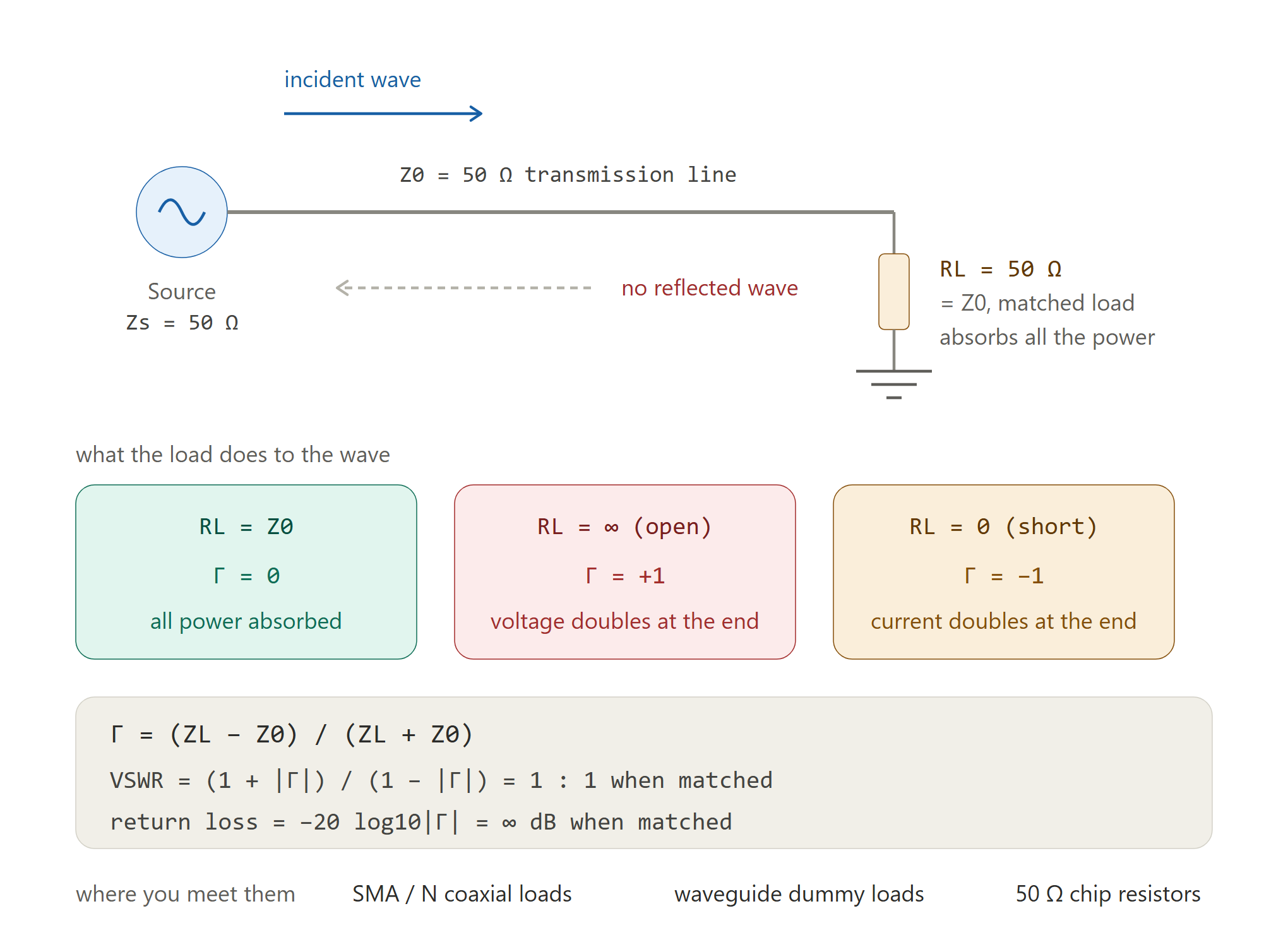
An RF termination is a load connected to a transmission-line port to provide a defined impedance. When the load impedance matches the characteristic impedance of the line, most of the incident power is absorbed instead of being reflected toward the source. A termination may be used on an unused splitter port, a test instrument port, a directional-coupler sample port, or the end of a coaxial cable.
A termination is not simply a resistor attached to a connector. At microwave frequencies, connector geometry, parasitic inductance and capacitance, construction, and electrical length all influence the impedance seen by the transmission line.
Why 50 ohms is widely used
A 50-ohm environment is common in RF and microwave instrumentation, communications equipment, antennas, and coaxial components. The value is a practical engineering standard that balances power-handling capability and attenuation for many coaxial cable designs. A 50-ohm source, cable, and load should be used together unless the system is deliberately designed for another impedance.
Do not connect a 50-ohm termination to a 75-ohm system and assume the mismatch is harmless. The reflection coefficient for a load is Γ = (ZL − Z0) / (ZL + Z0), where ZL is load impedance and Z0 is line impedance. The magnitude of Γ determines the reflected-wave amplitude.
Common types of RF terminations
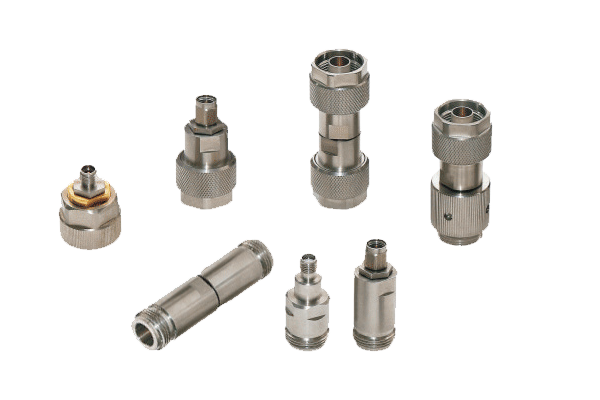
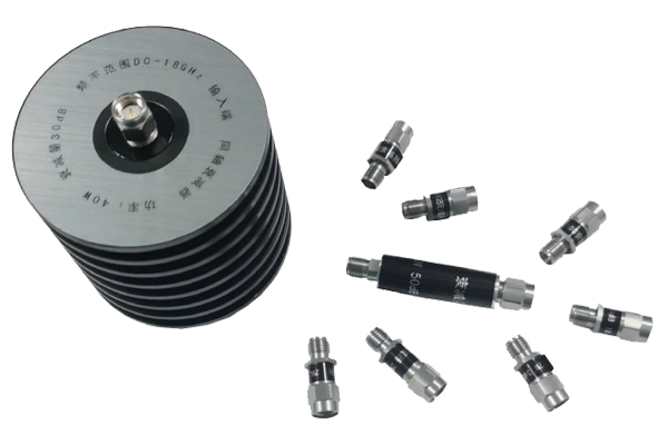
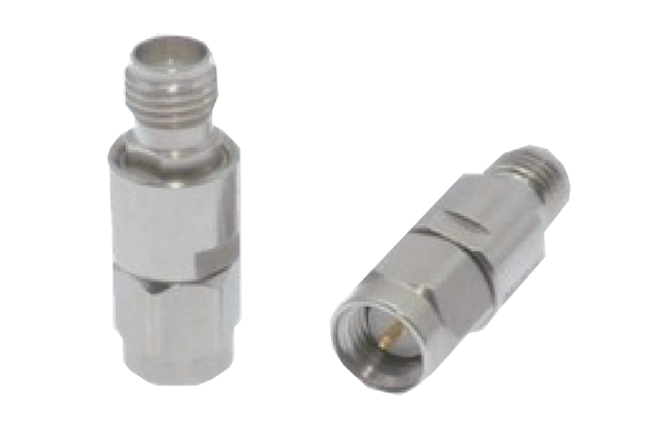
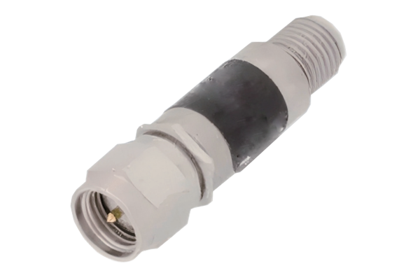
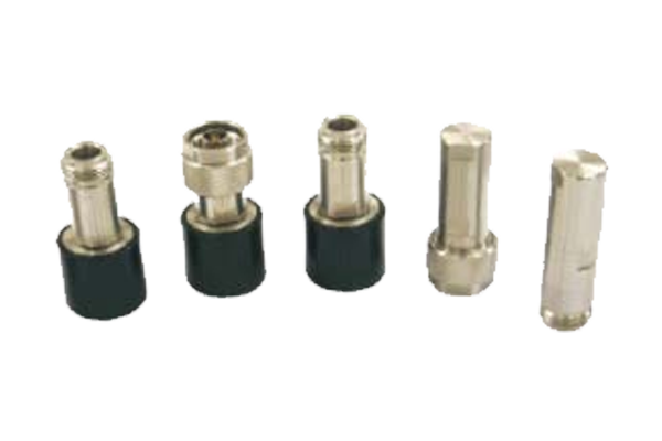
Coaxial terminations are available in connectorized formats such as SMA, N-type, 2.92 mm, 3.5 mm, 2.4 mm, and 1.85 mm, subject to the frequency and power limits of the specific design. Some are compact precision loads for vector network analyzer calibration and laboratory use; others are rugged loads for field or system integration.
A DC-blocked termination prevents DC from reaching the internal load, while a DC-pass design provides a conductive path. Some products include a heat sink or larger body to dissipate higher average power. Waveguide terminations are a separate component class and must match the waveguide band and flange interface.
Key specifications to compare
Frequency range defines the range over which the specified RF performance is maintained. VSWR or return loss indicates how closely the termination matches the system impedance. Average power rating describes continuous thermal capability under stated ambient and mounting conditions; peak power capability may be limited by pulse width, duty cycle, voltage breakdown, and connector design.
Also verify connector gender and interface, operating temperature, DC behavior, physical size, calibration status where relevant, and whether the published specifications apply across the entire frequency range. A low VSWR value at one frequency does not guarantee the same performance over the full band.
How to choose the right RF load
Start with the system impedance and connector interface. Next, identify the highest operating frequency and choose a termination whose specified range includes it with suitable margin. Determine the maximum average and peak incident power, including duty cycle for pulsed signals. Then compare VSWR, temperature range, mechanical robustness, and environmental requirements.
For precision measurements, use a characterized termination with performance appropriate to the instrument and calibration plane. For an unused port on a passive component, confirm that the termination's power rating and frequency range are adequate for the power that can reach that port.
Measurement and handling tips
Inspect connector interfaces before mating. Keep mating surfaces clean, avoid side loading, and use the connector manufacturer's recommended torque tool and value for the exact interface. Do not rotate the cable while tightening the coupling nut. If a termination becomes unusually hot, disconnect it safely after reducing RF power and investigate the applied power and cooling conditions.
A VNA can be used to measure return loss or VSWR when the device is within the instrument's frequency and power limits. Use a suitable calibration at the correct reference plane and avoid applying power beyond the termination's rating.
FAQ
Is an RF termination the same as an RF attenuator?
No. A termination is designed to present a specified load impedance at a port. An attenuator reduces signal level while maintaining a defined input and output impedance under its specified conditions.
Can I leave an RF port open?
An open port reflects incident energy and may disturb system behavior. Terminate unused ports when the component or system design requires it.
Does every RF termination have a 50-ohm impedance?
No. 50 ohms is common in RF coaxial systems, but 75-ohm and other impedance-specific products also exist. Match the termination to the system.