




DATE
June 9-11, 2026
LOCATION
Thomas M. Menino Convention & Exhibition Center
Boston, MA
May 26 ,26


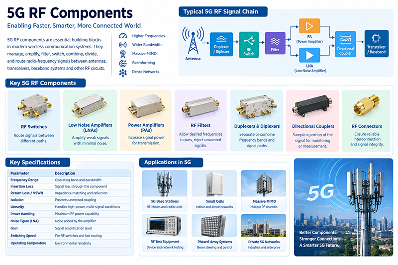
5G communication testing, wireless terminal automated testing
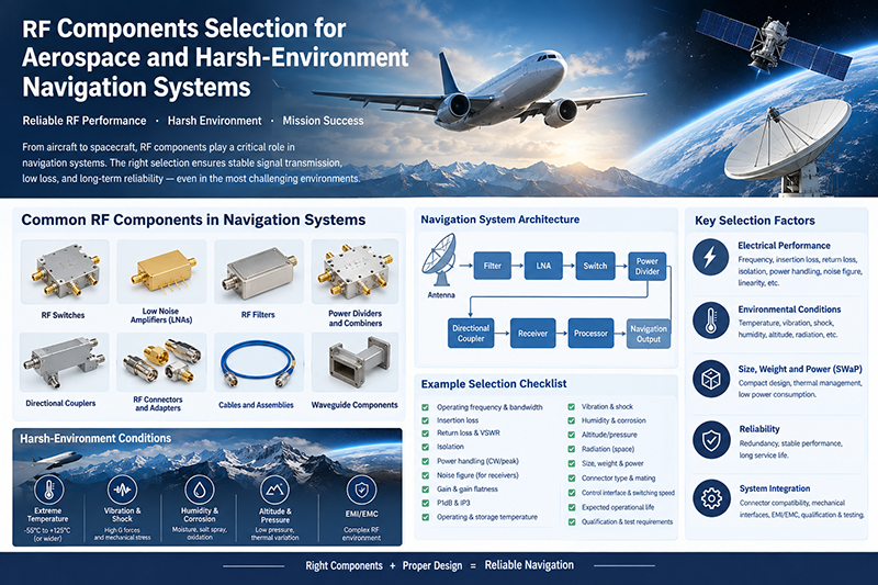
Aerospace communication systems
Precision measurement equipment, radio frequency signal control of radar transmitters
Communication and navigation systems
Optical communication module-related testing
Interconnection of wireless communication base stations
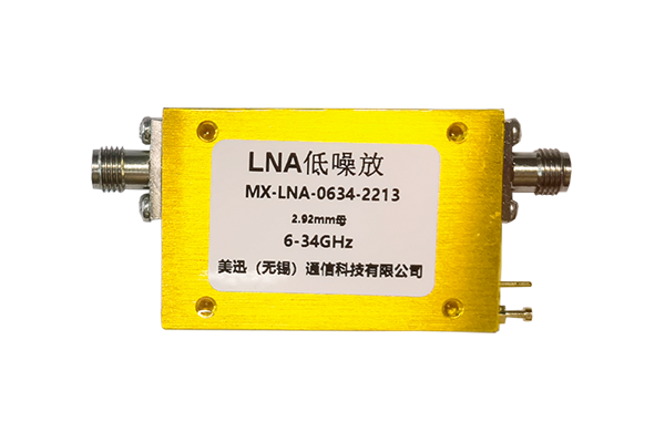
LNAs, filters, mixers and switches — what to choose for the LEO-to-GEO spectrum
Satellite communication — whether to LEO constellations like Starlink, MEO systems like O3b, or traditional GEO satellites like Intelsat — places some of the most demanding requirements on the RF chain. The signal arriving at the ground antenna is extraordinarily weak: a typical Ku-band GEO satellite signal arrives at −130 to −150 dBm at the antenna feed, after a 36,000 km path through free space. Closing the link budget requires an RF chain with the lowest possible noise, the highest possible linearity, and rock-solid stability.
Compared to terrestrial wireless systems (where signals are measured in −60 to −80 dBm), satcom RF operates in a regime where every tenth of a dB matters. The system designer's job is to chain together a low-noise amplifier, sharp bandpass filters, a stable mixer, a low-phase-noise synthesizer, and a high-precision data converter — all while minimizing losses between stages.
For satellite payloads (the on-orbit side of the link), the requirements are even harsher: components must survive launch vibration, the vacuum of space, temperature extremes of −40 to +85°C, and total ionizing dose from years of radiation exposure.
The first amplifier in any receiver chain dominates the system noise figure. Friis' formula for cascaded noise figure is:
NF_total = NF₁ + (NF₂ − 1) / G₁ + (NF₃ − 1) / (G₁ × G₂) + ...
Where NFi is the noise figure (linear) of stage i and Gi is the gain. The first stage's noise figure enters directly; subsequent stages' contributions are divided by the gain that precedes them. This means a low-noise first stage is far more important than low noise anywhere else.
Typical target noise figures for satcom LNAs:
• L-band (1–2 GHz): NF < 0.4 dB (used for legacy Inmarsat and GPS)
• S-band (2–4 GHz): NF < 0.4 dB
• C-band (4–8 GHz): NF < 0.5 dB
• X-band (8–12 GHz): NF < 0.6 dB (military satcom)
• Ku-band (12–18 GHz): NF < 0.8 dB
• Ka-band (26–40 GHz): NF < 1.5 dB
• V-band (50–75 GHz): NF < 3 dB
Place the LNA as close to the antenna feed as physically possible. Every meter of cable between the antenna and the LNA adds loss, which directly adds to the system noise figure. In professional ground stations, the LNA is often mounted directly on the antenna feed horn, with DC and control signals sent up the same coax using a bias tee.
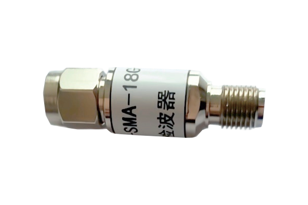
Bandpass filters are placed before and after the LNA to reject out-of-band interference and image frequencies. The filter after the LNA must have low insertion loss (because it sits in front of the next stage's noise contribution) but can have higher selectivity because the LNA's gain has already amplified the signal.
Filter technologies vary by frequency:
• Lumped-element LC: usable up to ~1 GHz. Small, low-cost, but lossy at higher frequencies.
• SAW (Surface Acoustic Wave): 0.1–3 GHz. Very sharp skirts, moderate loss, limited power handling.
• BAW (Bulk Acoustic Wave): 1–10 GHz. Sharper than SAW, smaller, more expensive.
• Ceramic monoblock: 0.5–6 GHz. Low loss, moderate selectivity.
• Cavity filters: 1–40 GHz. Highest Q, lowest loss, used in ground stations and satellite payloads.
• Dielectric filters: 1–40 GHz. Compact alternative to cavities.
For satellite payloads, where every fraction of a dB of loss matters, cavity or dielectric filters are used. For consumer ground terminals (Starlink dish, portable satcom terminals), ceramic or SAW filters are common.
After the LNA, the signal is down-converted to a lower intermediate frequency (IF) where it can be digitized and demodulated. The mixer's input third-order intercept point (IIP3) determines how well the receiver handles two strong out-of-band signals without generating intermodulation products that fall in-band. For satcom, mixers with IIP3 of +5 to +15 dBm are common.
The synthesizer (local oscillator) that drives the mixer must have low phase noise, because phase noise on the LO appears as noise at the mixer output, raising the receiver's noise floor. For low-rate data (voice, low-bitrate telemetry), phase noise requirements are modest. For high-rate data (broadband internet, video), phase noise must be below −90 dBc/Hz at 10 kHz offset or better.
For LEO constellations with high Doppler (Starlink at 550 km altitude has Doppler shifts of tens of kHz), the synthesizer must be able to retune quickly. DDS-based synthesizers with sub-Hz resolution and millisecond retune times are essential.
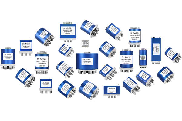
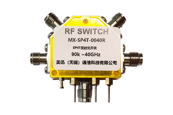
Satellite payloads and high-availability ground stations use latching coaxial switches to provide redundancy. If the primary LNA or downconverter fails, the switch transfers the antenna feed to a backup unit within milliseconds, and the system continues operating.
Latching switches hold their position without continuous current, which is critical for solar-powered platforms where every watt of standby power matters. The switch uses a brief pulse of current to change state, then latches mechanically or magnetically — no holding current required.
Redundancy architectures vary. 1:1 redundancy uses one backup for one primary, with a switch to choose between them. 1:N redundancy uses one backup for multiple primaries, with a larger switch matrix. M+N redundancy provides multiple backups per primary. Each additional level of redundancy adds weight, power, and complexity — the design tradeoff depends on the application's reliability requirements.
Components for satellite payloads must be space-qualified, which means surviving:
• Vibration: launch vehicles produce 10–20 g of random vibration and shock spikes up to 100 g.
• Thermal cycling: −40°C to +85°C (commercial), or −55°C to +125°C (military), often cycled hundreds of times.
• Vacuum: outgassing of materials can contaminate optical surfaces and other components.
• Radiation: total ionizing dose (TID) of 10–100 krad over a typical GEO mission. Single-event effects (SEE) from cosmic rays can flip bits or damage semiconductors.
• Atomic oxygen: in LEO, atomic oxygen erodes exposed surfaces.
Space-grade components are typically qualified to MIL-STD-883, MIL-PRF-38534, or ECSS standards. They are more expensive than commercial parts but have known reliability under extreme conditions.
Satellite communication uses specific frequency bands allocated by the ITU:
• L-band (1–2 GHz): Inmarsat, GPS, satellite phones. Good rain penetration, modest bandwidth.
• S-band (2–4 GHz): Some LEO downlinks, satellite radio (SiriusXM).
• C-band (4–8 GHz): Traditional GEO TV distribution, weather radar.
• X-band (8–12 GHz): Military satcom (AEHF, WGS).
• Ku-band (12–18 GHz): Direct-to-home TV, Starlink user downlink (10.7–12.7 GHz uplink, 11.7–12.2 GHz downlink in some regions).
• Ka-band (26–40 GHz): High-throughput satellites, Starlink (user + gateway), Viasat, Hughes Jupiter.
• V-band (50–75 GHz): Future high-throughput systems, intersatellite links.
• Optical: Emerging free-space optical communication (laser crosslinks).
The satcom RF chain starts with the link budget. Compute the required G/T (gain-to-noise-temperature ratio) for the ground station from the satellite EIRP, the path loss, and the required data rate and availability. Then work backward through the chain:
1. Select the LNA noise figure based on the G/T requirement.
2. Choose the LNA placement (at the feed horn for best noise, at the rack for easier maintenance).
3. Compute the down-conversion and IF chain gain or budget.
4. Verify linearity (P1dB, IP3) for the strongest expected signal (sun, satellite, radar).
5. Select filters with adequate selectivity for out-of-band rejection.
6. Design redundancy with latching switches.
7. Verify thermal management — the LNA may dissipate significant power in a sealed enclosure.
8. Specify calibration and monitoring — every component in a satcom chain should have telemetry.
Q: What is the best satcom LNA RF chain architecture? A: It depends on the application. For ground stations, an LNA at the feed horn followed by down-conversion at the rack is standard. For satellite payloads, direct conversion or low-IF receivers with extensive redundancy are common.
Q: How is a satcom RF chain different from a terrestrial wireless chain? A: Satcom signals are 50–80 dB weaker than terrestrial wireless, requiring LNAs with noise figures of 0.4–1.5 dB. Satcom also requires frequency stability over a wide Doppler range, especially for LEO systems.
Q: What is EIRP? A: Equivalent Isotropically Radiated Power — the transmit power multiplied by the antenna gain. Higher EIRP means the satellite can close the link to smaller ground antennas or at higher data rates.
Q: Can I use a commercial LNA for a satcom receiver? A: For ground stations, yes. For satellite payloads, no — only space-qualified parts are acceptable.
Q: What about Ka-band? A: Ka-band (26–40 GHz) is increasingly used for high-throughput satellite internet. The challenges are higher free-space path loss and increased rain fade, requiring larger ground antennas or higher link margins.
Satellite ground stations fall into three categories: fixed (large antennas at teleport facilities), mobile (ship, aircraft, vehicle-mounted), and portable (briefcase-sized terminals for emergency response). Each has different priorities. Fixed stations optimize for noise figure and reliability — they have ample space, AC power, and the budget for the best components. Mobile stations optimize for size, weight, and power (SWaP) — every gram and every milliwatt counts. Portable stations optimize for setup time and ease of use — they accept modest performance in exchange for fast operation in the field.
Link budget margins are critical for satcom. Atmospheric losses (rain, oxygen, clouds) can attenuate a Ku-band signal by 10 dB or more during heavy rain. Ka-band is even more sensitive — rain fade can exceed 20 dB. The link budget must include enough margin (typically 6–10 dB for availability 99.5% of the time, and 12+ dB for 99.9%) to handle these events. Adaptive coding and modulation (ACM) is now standard in modern satcom — the system reduces data rate during fade rather than losing the link entirely.
A LEO constellation user terminal (similar to Starlink) was experiencing link drops every 3 minutes as satellites passed overhead. The ground terminal's LNA and BUC (block upconverter) were properly designed, but the tracking algorithm was not accounting for Doppler shift on the up-link — at 1.5 GHz and orbital speed of 7.5 km/s, the up-link Doppler shift exceeded 30 kHz, larger than the carrier's lock-in bandwidth. The fix was a Doppler-prediction algorithm based on the satellite's known ephemeris, pre-compensating the synthesizer frequency. With the fix, the terminal maintained lock for the full 8-minute satellite pass instead of dropping every 3 minutes. The lesson: in LEO satcom, Doppler is a primary design driver, not a footnote.
Satellite communication RF is the most demanding of all RF engineering domains. The signals are weak, the noise floor is the lowest, and the consequences of design error are large. Take the time to design the link budget carefully, choose components with margin, and verify every assumption with measurement. The reward is a system that delivers years of reliable service in environments where replacement is difficult or impossible.
Across telecommunications, aerospace, defense, medical imaging, and automotive radar, the concepts covered in this guide show up in every RF design. From 5G base stations deploying massive MIMO antenna arrays with dozens of Wilkinson dividers per panel, to satellite payloads where every decibel of link budget determines the success of a multi-million-dollar mission, the principles remain the same: measure carefully, design with margin, and verify with the right instrument.
Medical applications add another wrinkle: MRI machines operate at the Larmor frequency of hydrogen (42.58 MHz/Tesla) and require extraordinarily low noise and high stability. Test systems for MRI receivers must minimize cable loss between the imaging coil and the low-noise preamplifier — often mounted directly on the coil housing — because every dB of loss degrades diagnostic image quality. The same matching, cabling, and LNA placement principles apply.
Automotive radar at 77 GHz is one of the fastest-growing RF domains. Each modern car may contain 5–10 mmWave radar units for adaptive cruise control, blind-spot detection, and automated emergency braking. These radar modules contain calibrated Wilkinson dividers, matched patch antennas, beam-steering phase shifters, and integrated FMCW synthesizers — all built on low-cost PCB substrates and tested in production at volumes exceeding 100 million per year. The principles taught in this guide are what make that volume manufacturing possible.
Beyond the basics covered above, several advanced topics deserve attention as your designs mature. Multi-physics simulation — coupling electromagnetic, mechanical, and thermal effects in a single simulation — is increasingly important at mmWave frequencies where small dimensional changes from thermal expansion can shift the operating frequency. Tools like ANSYS HFSS, CST Studio Suite, and Cadence Clarity now include multi-physics capabilities that integrate structural and thermal solvers with the RF simulator.
Machine learning is beginning to appear in RF design. Surrogate models trained on simulation data can predict S-parameters 1000× faster than running the full EM simulation, enabling design space exploration that was previously impossible. Tools like Google Brain's RF antenna design work and Cadence's Cerebrus are early examples of where the field is heading. For now, these tools augment rather than replace the engineer's judgment — they accelerate iteration but the final design still needs to be understood, verified, and signed off by an experienced engineer.
Every RF system must comply with applicable regulatory standards. In the United States, Part 15 of the FCC rules governs intentional radiators and unintentional emissions. The European Union's Radio Equipment Directive (RED) does similar work. Specific applications have additional standards: ETSI EN 301 893 for 5 GHz Wi-Fi, ETSI EN 302 500 for UWB, and many others. Military and aerospace applications have additional standards: MIL-STD-461 for EMI, MIL-STD-810 for environmental, and MIL-STD-1540 for product assurance.
Compliance testing is a discipline of its own. Compliance test labs use specialized instruments (spectrum analyzers with quasi-peak detectors, EMI receivers calibrated to CISPR standards) and follow specific procedures. The measurement uncertainty of compliance tests is typically ±3 to ±6 dB — much wider than production test measurements, but required for regulatory acceptance. Plan for compliance testing early in your design cycle; retrofitting a product to meet EMI requirements after the design is finalized is expensive and time-consuming.
RF engineering is a deep specialty with strong demand and excellent compensation. The barrier to entry is high: unlike software, you cannot iterate in seconds, and the cost of mistakes is paid in physical hardware. Yet for engineers who take the time to develop intuition, RF offers some of the most satisfying engineering work available — every component choice has a measurable effect, and every measurement reveals something about the physical world.
For those starting out, build a home lab. Even a modest setup with a cheap SDR (RTL-SDR, HackRF, or Airspy), a few antennas, and some cables will let you explore the RF spectrum in ways that no simulator can. Add a low-end spectrum analyzer (Rigexpert, TinySA) when you can afford it, and a used VNA from eBay when the budget allows. The hands-on experience with real signals, real cables, and real instruments is what builds intuition that no textbook can provide.
Stay current by reading industry publications (Microwave Journal, RF Globalnet, Microwaves & RF), attending conferences (IMS, EuMW, IEEE MTT-S), and joining professional communities (IEEE MTT-S, ACM SIGCOMM for networking RF). The field evolves rapidly — mmWave 5G, satellite internet, and automotive radar were niche markets 10 years ago and are now mainstream. The engineers who built those markets started by mastering exactly the fundamentals covered in this article.

High-tech Enterprise, Feifeng Talent
Chief Engineer Wang graduated with a master's degree in high-power microwave from the Institute of Electronics, University of Chinese Academy of Sciences.
View Full Profile