

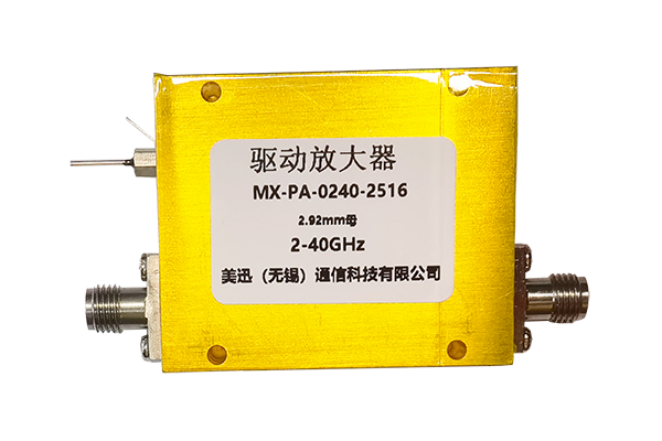




Voltage Standing Wave Ratio (VSWR) is one of the most important parameters in RF and microwave engineering. It indicates how effectively radio frequency power is transferred from a transmission line to a connected load, such as an antenna, RF amplifier, or microwave component.
A high VSWR indicates a significant impedance mismatch, meaning that more RF energy is reflected toward the source instead of being delivered to the load. This can reduce system efficiency, affect signal quality, and potentially damage sensitive RF equipment under certain operating conditions.
In this guide, we explain what VSWR means, how to calculate it, how it relates to return loss and reflected power, and how to measure it using professional RF test equipment. An interactive VSWR calculator is also included to help engineers quickly evaluate impedance matching performance.
1. What Is VSWR (Voltage Standing Wave Ratio)?
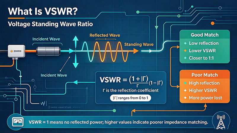
VSWR stands for Voltage Standing Wave Ratio. It describes the ratio between the maximum and minimum voltage amplitudes of a standing wave formed along a transmission line due to the interaction of incident and reflected RF signals.
When an RF signal travels through a transmission line and reaches a load, ideally all incident power should be absorbed by the load. However, if the load impedance does not match the characteristic impedance of the transmission line, a portion of the signal is reflected back toward the source.
The incident and reflected waves combine to produce a standing-wave pattern. The ratio between the maximum and minimum voltage amplitudes in this pattern is called VSWR.
How Does VSWR Work in an RF System?
Consider an RF transmitter connected to an antenna through a coaxial cable. If both the cable and antenna have a characteristic impedance of 50 ohms, the system should ideally transfer power efficiently.
If the antenna impedance changes because of frequency variation, installation conditions, nearby objects, or antenna damage, the load may no longer match the transmission line. Part of the RF energy is then reflected back toward the transmitter.
This reflected energy creates standing waves along the cable, and the resulting voltage distribution can be measured to determine VSWR.
2. VSWR Formula: How to Calculate Voltage Standing Wave Ratio
VSWR is calculated using the magnitude of the voltage reflection coefficient, commonly represented by |Γ| (Gamma).
The reflection coefficient describes the ratio of the reflected voltage wave to the incident voltage wave at a reference plane.
2.1 Calculate the Reflection Coefficient
The voltage reflection coefficient can be calculated from the load impedance and characteristic impedance of the transmission line:
For complex RF impedances, Γ is a complex quantity. Its magnitude is used to calculate VSWR.
2.2 Calculate VSWR from Forward and Reflected Power
If forward power and reflected power are known, the reflection coefficient magnitude can be calculated as:
Therefore, the VSWR formula becomes:
This method assumes that forward and reflected power are measured at the same reference plane with appropriate calibration and that the reflected power does not exceed the forward power.
2.3 VSWR Calculation Example
Suppose an RF system has a forward power of 100 watts and reflected power of 4 watts.
First, calculate the reflection coefficient:
Then calculate VSWR:
Therefore, the system has a VSWR of 1.5:1, indicating a relatively good impedance match.
3. Online VSWR Calculator
Use this free VSWR calculator to determine VSWR, reflection coefficient, return loss, and reflected power percentage. You can calculate the result using either a reflection coefficient or forward and reflected power measurements.
VSWR and Return Loss Calculator
Note: The calculator assumes ideal measurement conditions and a passive load. Actual RF measurements may be affected by calibration, cable losses, connector quality, and instrument directivity.
4. VSWR, Return Loss, and Reflected Power: What Is the Difference?
VSWR, return loss, and reflected power are closely related parameters used to evaluate impedance matching in RF and microwave systems. Although they describe the same underlying reflection phenomenon, each provides a different perspective.
VSWR
VSWR represents the ratio of maximum to minimum standing-wave voltage. It is a dimensionless ratio, usually expressed as 1.2:1, 1.5:1, or 2:1.
Return Loss
Return loss measures how much signal power is reflected back toward the source. It is expressed in decibels (dB). Higher return loss indicates better matching.
Reflected Power
Reflected power represents the portion of incident RF power returned by an impedance mismatch. It can be expressed in watts or as a percentage.
Mismatch Loss
Mismatch loss describes the reduction in power delivered to the load due to impedance mismatch, expressed in decibels.
Important Conversion Formulas
For example, a reflection coefficient of 0.2 corresponds to a return loss of approximately 13.98 dB, a reflected power of 4%, and a mismatch loss of approximately 0.18 dB.
5. VSWR Conversion Table
The following table shows the relationship between commonly used VSWR values, reflection coefficient, return loss, and reflected power.
| VSWR | Reflection Coefficient | Return Loss (dB) | Reflected Power |
|---|---|---|---|
| 1.00:1 | 0.0000 | Infinite | 0% |
| 1.10:1 | 0.0476 | 26.44 | 0.23% |
| 1.20:1 | 0.0909 | 20.83 | 0.83% |
| 1.30:1 | 0.1304 | 17.70 | 1.70% |
| 1.50:1 | 0.2000 | 13.98 | 4.00% |
| 1.80:1 | 0.2857 | 10.88 | 8.16% |
| 2.00:1 | 0.3333 | 9.54 | 11.11% |
| 2.50:1 | 0.4286 | 7.36 | 18.37% |
| 3.00:1 | 0.5000 | 6.02 | 25.00% |
| 5.00:1 | 0.6667 | 3.52 | 44.44% |
These values assume a passive load and a single reflection coefficient magnitude at the same reference plane. They are useful for evaluating antenna systems, RF switches, coaxial cables, connectors, and microwave components.
6. What Is a Good VSWR?
A good VSWR depends on the application, operating frequency, bandwidth, power level, and system requirements. There is no single acceptable VSWR value for every RF application.
| VSWR Range | General Evaluation | Typical Interpretation |
|---|---|---|
| 1.0–1.2 | Excellent | Very low impedance mismatch. |
| 1.2–1.5 | Very Good | Good matching for many RF systems. |
| 1.5–2.0 | Acceptable in some applications | Moderate reflection; verify system specifications. |
| 2.0–3.0 | Needs Evaluation | Significant impedance mismatch. |
| Above 3.0 | Poor | High reflected power; investigate the cause. |
These categories are general engineering guidelines, not universal pass/fail limits. For example, a high-performance microwave test system may require a much lower VSWR than a general-purpose communication antenna.
Why Is 1.5:1 VSWR Commonly Used?
A VSWR of 1.5:1 corresponds to approximately 4% reflected power and 13.98 dB return loss. It provides a useful balance between practical impedance matching requirements and manufacturing tolerances in many RF systems.
However, critical applications such as satellite communication, radar, phased-array antennas, and precision microwave measurements may require tighter matching specifications.
7. How to Measure VSWR: Step-by-Step Guide
VSWR can be measured using different types of RF test equipment. The appropriate method depends on the frequency range, required accuracy, power level, and measurement environment.
Method 1: Using a Vector Network Analyzer (VNA)
A Vector Network Analyzer is one of the most versatile instruments for VSWR measurement. It measures the complex reflection coefficient (S11) and converts it into VSWR and return loss.
- Prepare the equipment: Connect the VNA to the device under test using suitable RF cables and adapters.
- Set the frequency range: Configure the start frequency, stop frequency, and measurement points according to the device specifications.
- Perform calibration: Use an appropriate calibration method, such as SOL (Short, Open, Load), at the intended measurement reference plane.
- Connect the DUT: Attach the antenna, RF switch, amplifier, filter, or other component to the calibrated test port.
- Measure S11: Record the input reflection coefficient across the required frequency range.
- Display VSWR: Select the VSWR measurement format to evaluate impedance matching performance.
- Analyze the results: Identify frequencies where VSWR exceeds the specified limits.
A VNA is particularly useful for broadband characterization because it can show how VSWR changes across the operating frequency range.
Method 2: Using a Directional Coupler and RF Power Meter
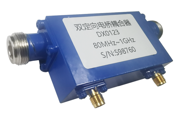
Another common approach is to use a directional coupler to separate forward and reflected signals. The power levels are then measured using RF power sensors or power meters.
- Connect the RF source to the input port of the directional coupler.
- Connect the device under test to the output port.
- Connect the forward and reflected coupling ports to suitable power measurement instruments.
- Measure forward power and reflected power under stable operating conditions.
- Calculate the reflection coefficient using the square root of the reflected-to-forward power ratio.
- Convert the reflection coefficient into VSWR using the standard formula.
The directional coupler must have sufficient directivity, frequency coverage, and power-handling capability. Poor directivity can introduce measurement errors, particularly when reflected power is low.
Method 3: Using a Dedicated VSWR Meter
A dedicated VSWR meter is often used in antenna testing, radio transmission systems, and field maintenance. It measures forward and reflected power and provides a direct VSWR reading.
This method is convenient for routine checks, although measurement bandwidth, calibration accuracy, power range, and instrument specifications should be considered.
8. Common Factors That Affect VSWR Measurements
Accurate VSWR measurement requires more than simply connecting an instrument. Several factors can affect the measured results.
Connector Quality
Damaged, contaminated, or improperly tightened RF connectors can introduce additional impedance discontinuities and reflections.
Cable Loss
Transmission line attenuation reduces the magnitude of reflected signals returning to the measurement instrument. This can make the apparent VSWR closer to 1:1 than the actual load-plane VSWR.
Calibration Errors
Incorrect calibration or an improperly established reference plane can affect S11 and VSWR measurements, especially at high frequencies.
Frequency Variation
Impedance matching changes with frequency. A component may have excellent VSWR at one frequency but perform poorly across a wider bandwidth.
Adapter and Fixture Effects
Additional connectors, adapters, and test fixtures introduce their own electrical characteristics and may affect measurement accuracy.
Measurement Directivity
Insufficient directional coupler directivity or VNA measurement isolation can limit the accuracy of low-reflection measurements.
9. VSWR Applications in RF and Microwave Engineering
9.1 Antenna Systems
VSWR is widely used to evaluate antenna impedance matching. A well-matched antenna transfers RF energy efficiently from the transmitter to the radiating element, reducing reflected power.
9.2 RF Coaxial Switches
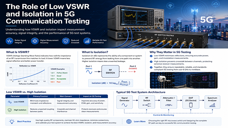
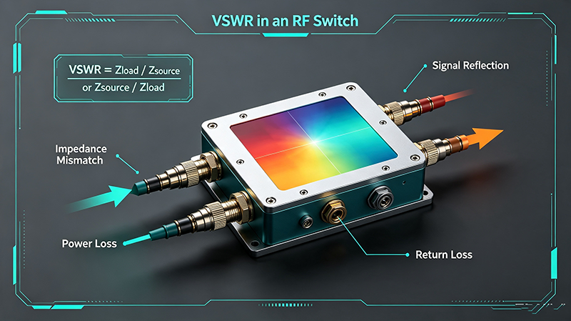
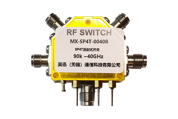
RF coaxial switches are used to route microwave signals between different signal paths. VSWR is an important performance specification because impedance discontinuities can affect signal integrity and overall system performance.
In high-frequency applications, engineers often evaluate VSWR together with insertion loss, isolation, repeatability, and power handling. These parameters are particularly important in automated RF test systems, radar equipment, satellite communications, and wireless infrastructure.
9.3 Waveguide Components
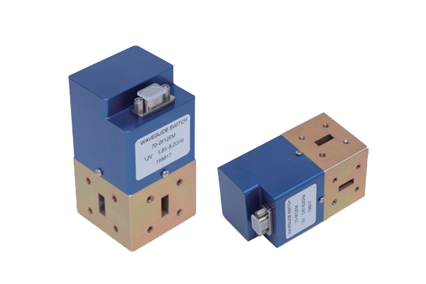
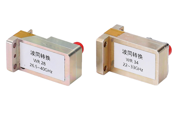
Waveguide switches, adapters, filters, and other microwave components must maintain suitable impedance matching across their operating frequency bands. VSWR is commonly used to evaluate the quality of waveguide transitions and connections.
9.4 RF Amplifiers and Transmitters
Impedance mismatch at the output of an RF power amplifier can increase reflected power and potentially trigger protection circuits or create excessive stress on the output stage.
Monitoring VSWR helps engineers verify system matching and identify problems caused by antennas, cables, connectors, or load conditions.
9.5 Microwave Testing and Measurement
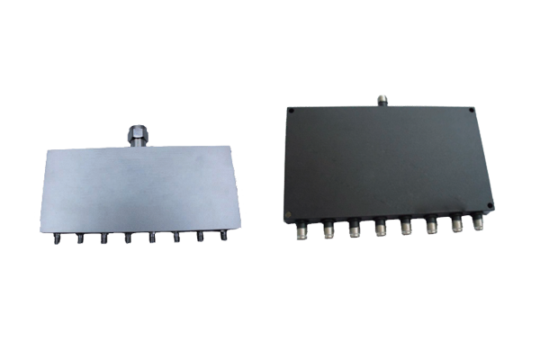
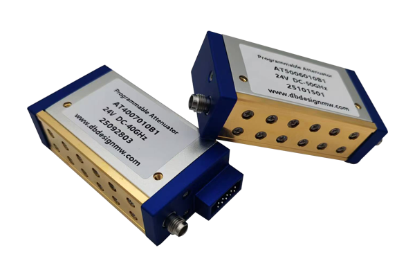
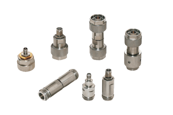
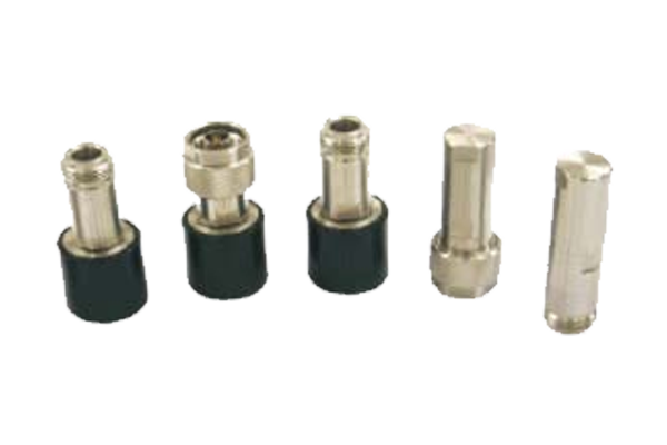
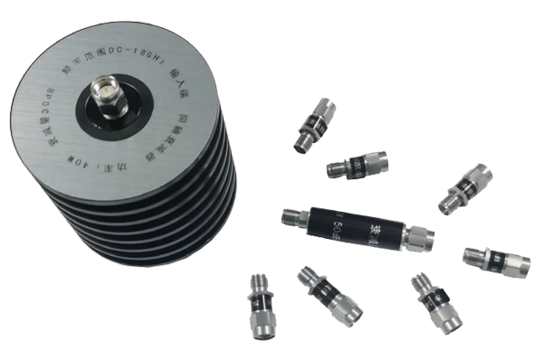
In microwave laboratories, VSWR is an important parameter for characterizing passive and active RF components. It helps engineers evaluate connectors, attenuators, power dividers, directional couplers, switches, and other microwave devices.
10. How to Reduce VSWR in an RF System
If measured VSWR exceeds the acceptable specification, the following engineering approaches can help identify and correct impedance mismatch problems.
- Verify impedance compatibility: Ensure that the source, transmission line, and load have compatible characteristic and input impedances. A 50-ohm system should generally use appropriately specified 50-ohm components.
- Inspect RF connectors: Check connector interfaces for damage, contamination, loose connections, or incorrect assembly.
- Use suitable matching networks: Depending on the application, L-networks, stub matching, quarter-wave transformers, or other impedance-matching techniques can reduce reflections.
- Check transmission lines: Inspect cables for physical damage, excessive bending, moisture ingress, and incorrect cable specifications.
- Evaluate component performance: Check the VSWR specifications of antennas, RF switches, adapters, and other connected components.
- Measure across the complete frequency range: A good VSWR reading at a single frequency does not guarantee broadband performance.
11. VSWR Measurement Equipment: What Should Engineers Choose?
Selecting the right instrument depends on the application and the required measurement accuracy.
| Instrument | Primary Function | Typical Application |
|---|---|---|
| Vector Network Analyzer | Measures complex S-parameters and VSWR | RF component characterization and laboratory testing |
| Directional Coupler | Separates forward and reflected signals | RF power monitoring and VSWR measurement systems |
| RF Power Meter | Measures RF signal power | Transmitter testing and reflected power analysis |
| VSWR Meter | Displays voltage standing wave ratio | Antenna installation and field maintenance |
| Spectrum Analyzer with Suitable Reflection Measurement Setup | Analyzes signal characteristics and, with appropriate external hardware, reflection-related measurements | RF troubleshooting and signal analysis |
For precision RF and microwave applications, a calibrated VNA is generally preferred because it provides frequency-dependent reflection measurements and supports detailed S-parameter analysis.
12. Frequently Asked Questions About VSWR
Q1: What does VSWR stand for?
VSWR stands for Voltage Standing Wave Ratio. It measures the ratio of maximum to minimum voltage amplitude in the standing-wave pattern along a transmission line.
Q2: What is a perfect VSWR value?
A perfect VSWR is 1:1. This represents an ideal impedance match with a reflection coefficient of zero and no reflected power.
Q3: Is a VSWR of 1.5 good?
Yes. A VSWR of 1.5:1 corresponds to approximately 4% reflected power and 13.98 dB return loss. It is acceptable for many RF applications, although the final requirement depends on the equipment specifications.
Q4: How do I calculate VSWR from return loss?
First calculate the reflection coefficient using |Γ| = 10^(-RL/20), where RL is return loss in dB. Then use VSWR = (1 + |Γ|)/(1 - |Γ|).
Q5: What is the difference between VSWR and return loss?
VSWR is a dimensionless ratio describing the standing-wave voltage distribution, while return loss is expressed in decibels and indicates the amount of reflected signal power. Higher return loss generally corresponds to lower VSWR.
Q6: Can VSWR be greater than 10?
Yes. A VSWR greater than 10 indicates a severe impedance mismatch. In practical systems, this may result from an open circuit, short circuit, damaged cable, or poorly matched load.
Q7: Does cable length affect VSWR?
For an ideal, lossless transmission line, changing cable length changes the phase of the reflection coefficient at the input but not its magnitude or VSWR. In real systems, cable losses and measurement reference-plane effects can change the observed VSWR.
Q8: Can a VNA measure VSWR?
Yes. A Vector Network Analyzer measures the reflection coefficient through S11 and can display VSWR, return loss, and other impedance-related parameters.
Q9: What causes high VSWR in an antenna system?
Common causes include antenna impedance mismatch, incorrect installation, damaged coaxial cables, poor connector connections, nearby conductive objects, and operating outside the antenna's intended frequency range.
Q10: What is the relationship between VSWR and reflected power?
Reflected power percentage equals the square of the reflection coefficient magnitude multiplied by 100. A higher VSWR means a larger reflection coefficient and a greater percentage of reflected power.
13. Conclusion
VSWR is a fundamental measurement parameter for evaluating impedance matching in RF and microwave systems. Understanding the relationship between VSWR, reflection coefficient, return loss, and reflected power enables engineers to assess signal transmission efficiency and identify potential performance problems.
Whether testing antennas, coaxial switches, waveguide components, RF amplifiers, or microwave transmission systems, accurate VSWR measurement is essential for reliable system performance.
By using a calibrated Vector Network Analyzer, suitable directional couplers, and proper measurement procedures, engineers can obtain reliable results and improve the performance of their RF systems.
Looking for High-Performance RF and Microwave Components?
Reliable RF switches and microwave components are essential for maintaining signal integrity, low reflection, and stable system performance. Explore professional RF and microwave solutions from MeiXun for demanding test and measurement, communication, radar, and aerospace applications.