Selecting the optimal Low Noise Amplifier for your RF receiver requires a systematic approach that balances performance, cost, power, and integration requirements. This comprehensive guide walks you through a proven six-step selection process, helping you identify the best LNA for your specific application while avoiding common pitfalls.
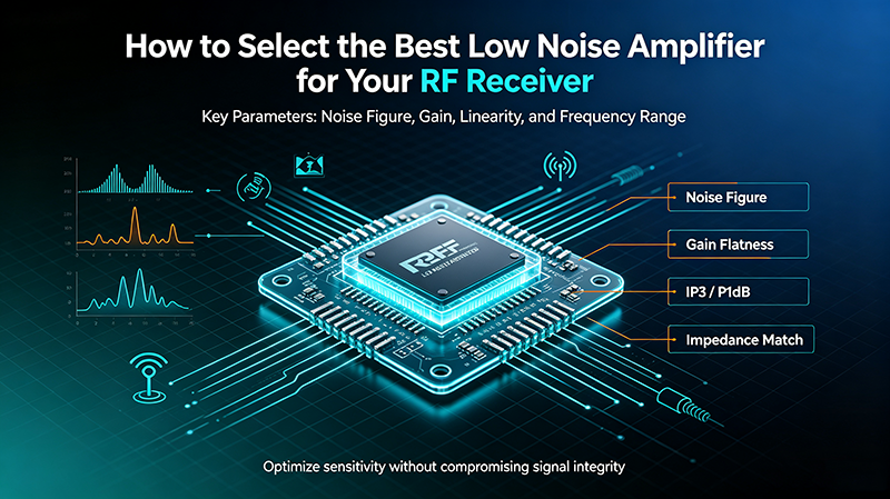
Define Receiver Requirements
Before evaluating any LNA candidates, clearly define your receiver's key performance requirements. These specifications drive all subsequent selection decisions.
Key Requirements to Document
Primary Specifications
- Operating Frequency Range: Minimum and maximum frequencies
- Required Sensitivity: Minimum detectable signal level (dBm)
- System Noise Figure Budget: Maximum allowable NF
- Dynamic Range Requirements: From MDS to maximum signal
- Bandwidth: Instantaneous bandwidth needed
- Channel Spacing: For multi-channel systems
Environmental and Operational Constraints
- Operating temperature range
- Available supply voltages and power budget
- Size and weight limitations
- Reliability and lifetime requirements
- Compliance standards (CE, FCC, MIL-SPEC)
Sensitivity = -174 + 10*log10(BW) + NF + SNR_min (in dBm)
Calculate Cascade Noise Figure Budget
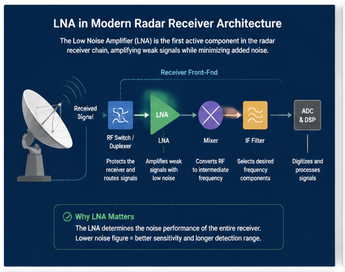
Use Friis cascade formula to determine what NF and gain your LNA must provide to achieve the overall system noise figure target.
NF_total = NF1 + (NF2-1)/G1 + (NF3-1)/(G1*G2) + ...
Cascade Analysis Example
| Stage | NF (dB) | Gain (dB) | NF Contribution |
|---|---|---|---|
| Antenna | 0 | 0 | 0 dB |
| LNA | 1.0 | 20 | 1.0 dB |
| Filter | 1.5 | -1.5 | 0.001 dB |
| Mixer | 8 | -7 | 0.05 dB |
| IF Amplifier | 2 | 30 | Negligible |
| Total | - | - | 1.05 dB |
LNA NF and Gain Requirements
Calculate Required LNA Performance
- Determine total system NF target from sensitivity requirements
- Calculate NF contributions of all subsequent stages
- LNA NF target = Total NF target - small margin (0.1-0.3 dB)
- LNA gain should be > 15-20 dB to swamp subsequent stage noise
- Avoid excessive gain (>30 dB) that reduces linearity
Key Principle
The LNA's noise figure dominates system NF only when its gain is sufficient to make subsequent stages' noise contributions negligible. Aim for at least 15-20 dB of LNA gain to achieve this effect.
Identify Frequency and Bandwidth
Frequency range and bandwidth significantly narrow your LNA choices. Different technologies excel at different frequency ranges.
Frequency-Based Technology Selection
VHF/UHF (0.03-1 GHz)
SiGe BiCMOS or CMOS LNAs offer good performance and low cost. GaAs becomes beneficial above 500 MHz.
L/S-Band (1-4 GHz)
GaAs pHEMT dominates with excellent NF below 1 dB. SiGe also competitive for cost-sensitive apps.
C/X-Band (4-12 GHz)
GaAs pHEMT is industry standard. GaN emerging for high-linearity applications.
Ku/Ka-Band (12-40 GHz)
InP HEMT provides lowest NF. GaAs still common. GaN for high-power applications.
V/W-Band (50-110 GHz)
Specialized InP and advanced GaN processes required. Research-grade components only.
Sub-THz (>110 GHz)
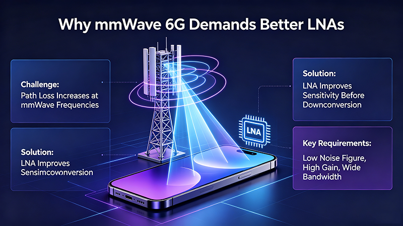
Cutting-edge research components. Limited commercial availability for 6G and scientific applications.
Bandwidth Considerations
- Narrowband: Allows optimized matching at specific frequency for best NF
- Wideband: Maintains performance across broad spectrum but compromises peak NF
- Multi-band: Modern designs use single LNA for multiple bands
- Tunable: Digitally controlled LNAs for software-defined radio
Evaluate Linearity Requirements
Linearity requirements depend on the strongest expected signals at the LNA input and the modulation scheme used in your system.
Linearity Parameter Requirements
Calculate Required Linearity
- Input P1dB: Must exceed maximum expected input signal
- Input IP3: Determines intermodulation performance with two signals
- Spurious-Free Dynamic Range: SFDR = 2/3 * (IIP3 + 174 - 10*log10(BW) - NF)
- Modulation Considerations: Higher-order modulation (256-QAM, 1024-QAM) needs better linearity
- Blocker Tolerance: Must handle out-of-band strong signals
SFDR (dB) = 2/3 * (OIP3 - NF - 10*log10(BW) + 174)
Technology Selection by Linearity
| Application | OIP3 Required | Recommended Tech |
|---|---|---|
| Weak Signal Reception | +5 to +10 dBm | GaAs pHEMT |
| 5G Infrastructure | +10 to +20 dBm | GaN HEMT |
| Radar Receivers | +15 to +25 dBm | GaN HEMT |
| Test Equipment | +20 to +30 dBm | GaN HEMT |
Consider Power and Thermal Constraints
Power consumption affects battery life, thermal management, and operating costs. Carefully evaluate power requirements for your application.
Power Budget Categories
Ultra-Low Power (<50 mW)
IoT sensors, wearables, battery-powered devices. CMOS technology typically used with reduced performance trade-offs.
Low Power (50-200 mW)
Mobile devices, portable instruments. SiGe or CMOS LNAs balance performance and efficiency.
Standard (200-500 mW)
Infrastructure equipment, fixed installations. GaAs provides excellent performance at moderate power.
High Power (>500 mW)
Defense systems, high-linearity applications. GaN delivers superior linearity and power handling.
Thermal Management
- Calculate junction temperature from power dissipation
- Ensure adequate thermal dissipation path
- Use thermal vias and copper pour areas
- Consider ambient temperature extremes
- Account for heat from adjacent components
Tj = Ta + Pdiss * Rtheta_JC * Rtheta_CS * Rtheta_SA
Compare and Validate Candidates
After narrowing your candidates based on technical requirements, validate your choices through evaluation, simulation, and manufacturer support assessment.
Final Comparison Criteria
Evaluate Candidate LNAs
- Request evaluation boards from manufacturers
- Compare total cost including external components
- Verify package size and mounting requirements
- Check manufacturer reliability track record
- Review application notes and reference designs
- Confirm supply chain availability and lifecycle
- Assess technical support quality
Validation Process
- Bench Testing: Measure actual NF, gain, IP3 with your signal sources
- Environmental Testing: Verify performance across temperature range
- System Integration: Test with full receiver chain
- Long-term Reliability: Run accelerated life tests if critical application
- EMI/EMC Compliance: Verify regulatory requirements
Final Selection Decision Flow
Does it meet all technical requirements?
If yes, proceed. If no, return to step 3 and identify alternative candidates.
Is total cost within budget?
Include unit cost, external components, qualification costs, and lifecycle costs.
Can you obtain reliable supply?
Verify multiple sources, distributor availability, and manufacturer longevity.
Is manufacturer support adequate?
Check technical documentation, application support, and warranty terms.
Pro Tip: Don't Optimize One Parameter
The best LNA for your application balances all requirements. Choosing based solely on lowest NF, highest gain, or lowest cost often leads to suboptimal system performance. Use weighted scoring if multiple candidates meet technical requirements.
Application-Specific Selection Guidance
Different applications have unique priorities that affect LNA selection. Here are recommendations for common RF receiver applications.
GPS/GNSS Receivers
Priority: Ultra-low NF (<1 dB), low power, single L-band frequency
Recommendation: Specialized GaAs pHEMT LNAs with integrated filters
Cellular Base Stations
Priority: High linearity for 5G, multi-band operation, reliability
Recommendation: GaN LNAs or integrated front-end modules
Satellite Ground Stations
Priority: Lowest possible NF, high gain, specific satellite bands
Recommendation: InP HEMT LNAs with cryogenic cooling for premium systems
Automotive Radar
Priority: 77/79 GHz operation, AEC-Q100 qualified, reliability
Recommendation: SiGe or GaAs LNAs specifically designed for automotive
Test Equipment
Priority: Wide bandwidth, high linearity, flat gain
Recommendation: Premium GaAs or GaN LNAs from established manufacturers
IoT Devices
Priority: Ultra-low power, low cost, adequate NF
Recommendation: CMOS or SiGe LNAs with sleep modes
Frequently Asked Questions
Conclusion
Selecting the best LNA for your RF receiver requires a systematic approach that considers all performance requirements, environmental constraints, and application priorities. The six-step process outlined in this guide provides a proven framework for making informed LNA selections.
Remember that the optimal LNA is not always the one with the best individual specifications. Consider the entire receiver system, including all stages, environmental conditions, and total lifecycle costs. Use the application-specific guidance to identify technology preferences and common pitfalls to avoid.
By following this systematic selection process and validating your choices through bench testing and evaluation, you can identify the LNA that provides the best balance of performance, cost, and reliability for your specific RF receiver application.
Need Expert Help with LNA Selection?
Our engineering team can help you navigate the selection process and identify the optimal LNA for your specific receiver application.
Contact Our Technical Team