

























The complete guide to Low Noise Amplifiers (LNAs): technical principles, applications, selection criteria, and leading manufacturers for 5G, radar, satellite, and SDR systems.
Sep 18 ,26


5G communication testing, wireless terminal automated testing
Aerospace communication systems
Precision measurement equipment, radio frequency signal control of radar transmitters
Communication and navigation systems
Optical communication module-related testing
Interconnection of wireless communication base stations
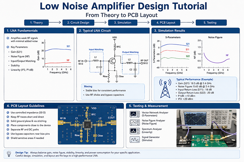
A Low Noise Amplifier (LNA) is one of the most important components in modern RF and microwave receiver systems. It is designed to amplify extremely weak signals while adding as little noise as possible. LNAs are widely used in radar systems, satellite communication, wireless networks, electronic warfare, test equipment, and other high-frequency applications.
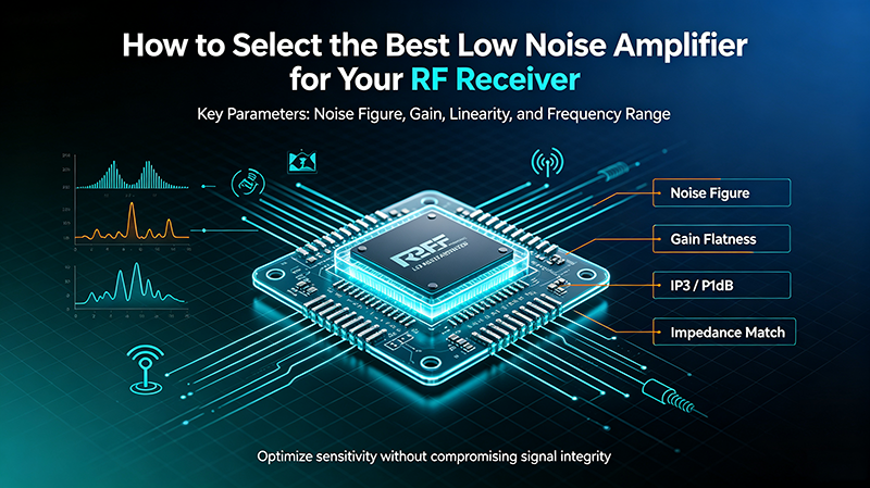
Selecting the right LNA requires a deep understanding of key specifications such as gain, noise figure, 1dB compression point (P1dB), and third-order intercept point (IP3). These parameters directly affect receiver sensitivity, dynamic range, signal quality, and overall system performance.

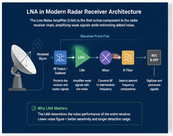
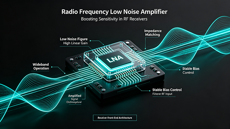
A Low Noise Amplifier is an RF amplifier placed at the front end of a receiver chain. Its primary function is to increase the power level of weak incoming signals while maintaining a low noise contribution.
Because the LNA is usually the first active component after the antenna, its performance has a significant impact on the entire receiver system. According to the Friis noise formula, the noise characteristics of the first amplifier stage dominate the total receiver noise figure.
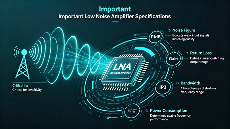
| Specification | Description | Impact on System Performance |
|---|---|---|
| Gain | The ability of the LNA to increase signal power | Improves signal level and compensates for transmission losses |
| Noise Figure | The amount of noise added by the amplifier | Determines receiver sensitivity |
| P1dB | The input/output power level where gain compression begins | Defines maximum linear operating power |
| IP3 | A measurement of amplifier linearity | Indicates resistance to intermodulation distortion |
Gain is one of the most commonly referenced specifications of a Low Noise Amplifier. It represents the ratio between output power and input power, normally expressed in decibels (dB).
For example, an LNA with 20 dB gain increases the input signal power by approximately 100 times. Higher gain can improve receiver sensitivity by boosting weak signals before further processing stages.
However, excessive gain may cause instability, higher power consumption, and reduced dynamic range. Therefore, selecting the appropriate gain level is critical for RF system design.
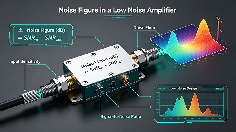
Noise figure (NF) describes how much additional noise an amplifier introduces into a signal. It is usually measured in decibels (dB).
A lower noise figure means better amplifier performance and higher receiver sensitivity. For many communication and radar applications, achieving an extremely low noise figure is a primary design goal.
High-performance microwave LNAs commonly achieve noise figures below 1 dB in specific frequency bands, making them suitable for demanding applications such as satellite receivers and aerospace systems.
The 1dB compression point (P1dB) defines the input or output power level where the amplifier gain decreases by 1 dB from its ideal linear value.
When an LNA operates near or beyond its P1dB point, signal distortion increases and receiver performance degrades.
Third-order intercept point (IP3) is a key parameter used to evaluate RF amplifier linearity. It describes how well an amplifier handles multiple signals without generating unwanted intermodulation products.
A higher IP3 value indicates better linearity and improved resistance against distortion. This is especially important in crowded RF environments where multiple signals exist simultaneously.
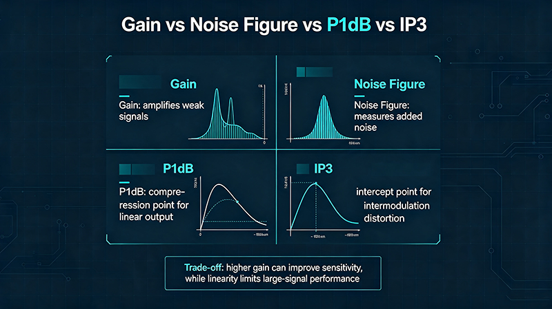
RF engineers must evaluate multiple specifications together rather than focusing on a single parameter. Improving one specification may negatively affect another.
| Design Goal | Important Parameter |
|---|---|
| Maximum receiver sensitivity | Low Noise Figure |
| Strong signal amplification | High Gain |
| High input power handling | High P1dB |
| Low distortion performance | High IP3 |
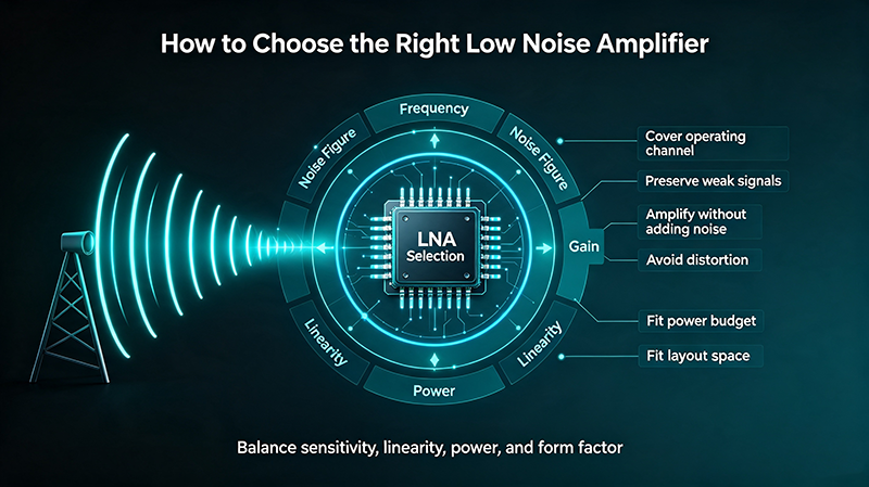
When selecting an LNA for an RF or microwave system, engineers should consider:
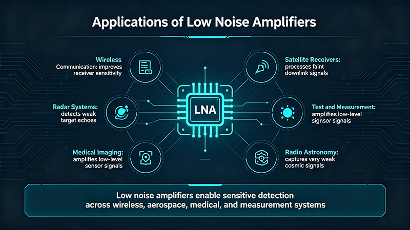
Low Noise Amplifiers are widely used in many advanced RF systems, including:
Understanding Low Noise Amplifier specifications is essential for designing high-performance RF receiver systems. Parameters such as gain, noise figure, P1dB, and IP3 determine how effectively an LNA can amplify weak signals while maintaining signal integrity.
Whether used in radar, satellite communication, wireless networks, or microwave test systems, selecting the right Low Noise Amplifier requires careful consideration of performance requirements and application conditions.
Professional microwave LNA manufacturers provide customized solutions with optimized gain, low noise figure, wide frequency coverage, and excellent linearity for advanced RF applications.

High-tech Enterprise, Feifeng Talent
Chief Engineer Wang graduated with a master's degree in high-power microwave from the Institute of Electronics, University of Chinese Academy of Sciences.
View Full Profile