


























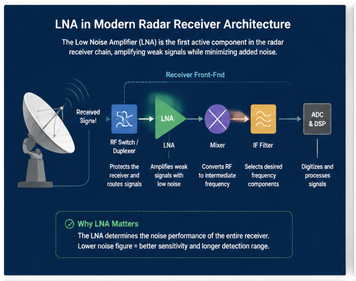
A Low Noise Amplifier (LNA) plays a critical role in radar receiver architectures by amplifying low-level RF signals while introducing minimal additional noise.
Aug 05 ,26


5G communication testing, wireless terminal automated testing
Aerospace communication systems
Precision measurement equipment, radio frequency signal control of radar transmitters
Communication and navigation systems
Optical communication module-related testing
Interconnection of wireless communication base stations
Low Noise Amplifiers (LNAs) are critical components in radar receiver systems because they determine the overall sensitivity, detection range, and signal quality of the radar system. Designing an LNA with high gain stability requires careful optimization of noise performance, gain flatness, impedance matching, feedback control, and device selection.
This guide explains the key design techniques for developing high-performance LNAs with stable gain characteristics for modern radar applications, including military radar, automotive radar, weather radar, and aerospace communication systems.
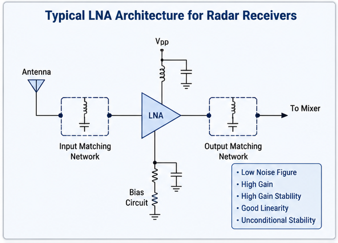
Radar receivers operate under demanding conditions where input signals can vary significantly due to target distance, environmental changes, and interference. An unstable LNA gain can introduce amplitude errors, reduce detection accuracy, and degrade radar tracking performance.
High gain stability ensures that the amplifier maintains consistent signal amplification across temperature variations, frequency changes, and supply voltage fluctuations.
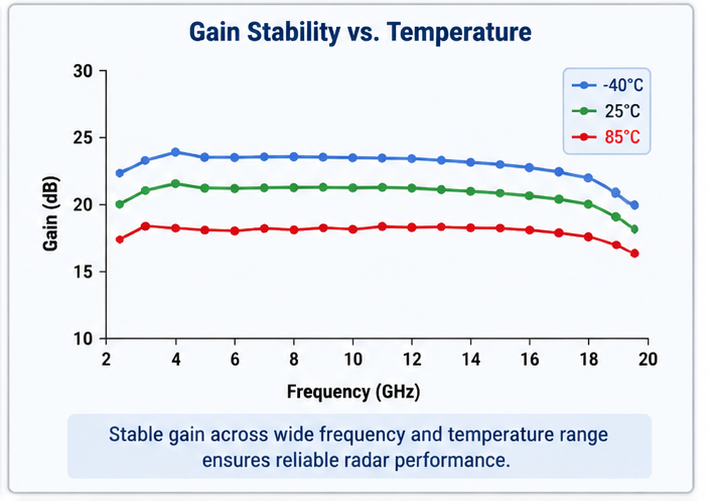
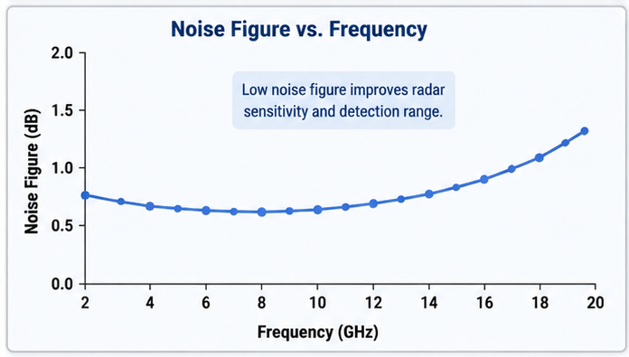
A radar receiver LNA design must balance several RF performance parameters. The most important specifications include:
| Parameter | Design Importance |
|---|---|
| Noise Figure (NF) | Determines receiver sensitivity and minimum detectable signal level. |
| Gain | Provides sufficient amplification while maintaining signal integrity. |
| Gain Stability | Ensures consistent amplification over temperature, voltage, and frequency changes. |
| Input Return Loss | Improves impedance matching and reduces signal reflection. |
| Linearity | Prevents distortion from strong interfering signals. |
| Isolation | Reduces feedback and unwanted oscillation. |
The semiconductor technology used in an LNA directly affects gain stability and noise performance. Common choices include GaAs pHEMT, GaN HEMT, and CMOS RF devices.
GaAs pHEMT technology is widely used in radar LNAs because of its excellent noise figure, high gain, and strong microwave performance. It is suitable for X-band, Ku-band, and higher frequency radar systems.
GaN devices provide high power handling capability and improved reliability in high-temperature environments. They are often used in advanced radar systems requiring high dynamic range.
CMOS technology offers low cost and high integration, making it attractive for automotive radar and compact radar modules.
Stable biasing is essential for maintaining constant transistor operating conditions. Variations in drain current or gate voltage can directly affect gain performance.
Designers should use temperature compensation circuits, voltage regulators, and carefully selected bias components to minimize gain drift.
Feedback can improve gain stability by reducing sensitivity to device parameter variations. Although excessive feedback may increase noise figure, properly optimized feedback networks can provide a good balance between stability and noise performance.
Input and output matching networks significantly influence gain variation. Poor matching can create frequency-dependent gain peaks and unstable operation.
RF simulation tools such as Keysight ADS and Cadence AWR are commonly used to optimize matching networks before PCB fabrication.
Temperature changes can alter transistor characteristics, causing gain drift. Thermal management methods include:
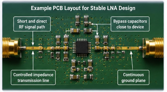
Even a well-designed circuit can suffer performance degradation due to poor PCB layout. RF layout directly impacts gain stability, noise figure, and oscillation risk.
Simulation and measurement are essential for verifying radar LNA performance.
Engineers typically analyze:
Common measurement equipment includes:
| Problem | Possible Cause |
|---|---|
| Gain fluctuation | Bias instability or temperature variation |
| Unexpected oscillation | Poor isolation or excessive feedback |
| Frequency-dependent gain peaks | Incorrect impedance matching |
| High noise figure | Poor transistor selection or matching network design |

Stable high-performance LNAs are widely used in:
Designing a low noise amplifier with high gain stability for radar receivers requires a comprehensive approach involving device selection, bias optimization, impedance matching, thermal control, and rigorous RF testing.
By carefully managing gain variation, noise performance, and circuit stability, engineers can develop reliable LNAs that deliver superior radar sensitivity and accuracy in demanding applications.
High-tech Enterprise, Feifeng Talent
Chief Engineer Wang graduated with a master's degree in high-power microwave from the Institute of Electronics, University of Chinese Academy of Sciences.
View Full Profile