Wilkinson Power Divider: Design Principles, Isolation, and Applications
The classic 2-way splitter that revolutionized RF design
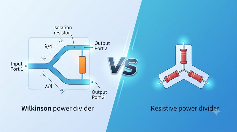
Figure 1 — Wilkinson Power Divider Schematic
What Is a Wilkinson Power Divider?
The Wilkinson power divider is a three-port passive device that splits an input signal into two equal-amplitude, equal-phase outputs, while keeping all three ports matched and providing high isolation between the output ports. When used in reverse — with two inputs and one output — it acts as a lossless 2-way power combiner. Invented by Ernest Wilkinson in 1960, it remains the workhorse 2-way power splitter for RF and microwave engineering.
The Wilkinson divider has three defining properties: it splits power equally, it has all ports at Z₀ impedance, and it has high isolation between output ports (typically 20–30 dB or more). These three properties are not all available in simpler dividers — a T-junction, for example, has none of them.
Why It's Special
Unlike a simple T-junction, a Wilkinson divider is matched at all ports and provides isolation between outputs — meaning a mismatch at one output does not appear at the other. The 100 Ω resistor between the two output arms absorbs the imbalance that would otherwise be reflected.
When you split a signal with a T-junction, any mismatch at one output causes power to reflect back and partly appear at the other output (poor isolation). With a Wilkinson, that reflected power is dissipated in the isolation resistor instead of crossing over. For receivers, this means a local oscillator's noise does not leak from one channel into the other. For transmitters, it means mismatch on one antenna does not pull the other antenna off-tune.
Design Equations
For a 2-way Wilkinson divider on a substrate with characteristic impedance Z₀ = 50 Ω, the design is straightforward:
Each branch: a quarter-wave transmission line of impedance √2·Z₀ ≈ 70.7 Ω.
Isolation resistor between the two output branches: 2·Z₀ = 100 Ω.
The quarter-wave lines transform the 50 Ω load impedances at the output ports into 100 Ω at the input node, which then combines in parallel to present 50 Ω to the source. The isolation resistor connects the two output arms directly; it absorbs any differential signal that would otherwise leak between outputs but does not dissipate any power when both outputs are matched.
Even- and Odd-Mode Analysis
The Wilkinson divider's behavior is most elegantly understood through even- and odd-mode analysis. Apply a signal at the input port — this is the 'even mode' excitation, where both output arms carry equal amplitude and phase. The isolation resistor sees zero voltage across it (because both ends are at the same potential) and dissipates no power. Each output receives half the input power, with 3 dB of insertion loss (the fundamental loss of any lossless 2-way splitter).
Apply two signals of opposite phase at the two outputs — this is the 'odd mode' excitation. The isolation resistor now has voltage across it and dissipates the differential power. The input port is isolated from this mode by the quarter-wave lines, which transform the odd-mode short at the input into an open circuit at the resistor. This combination of even-mode transmission and odd-mode absorption is what gives the Wilkinson its matched ports and high isolation.
Bandwidth and Limitations
A single-section Wilkinson is narrowband — about 20–30% fractional bandwidth. The bandwidth is limited by the quarter-wave lines, which only transform impedances correctly at their design frequency (and degrade rapidly with frequency deviation).
For wider bandwidth, use a multi-section Wilkinson, where each section is a quarter-wave line with progressively varying impedance. A 2-section Wilkinson achieves roughly 50% bandwidth; a 3-section achieves 80% or more. Each section adds insertion loss of ~0.05–0.2 dB.
Stepped-impedance variants use multiple impedances within each quarter-wave section, optimizing both bandwidth and physical length. These are the highest-performance designs but also the most complex to manufacture.
Microstrip vs. Stripline
The transmission lines can be implemented in several media, each with trade-offs:
• Microstrip: cheapest and easiest to fabricate on standard PCB. The trace is on the top surface and the ground plane is on the bottom. Slight asymmetry means the divider is not perfectly balanced at high frequencies, but for most applications this is acceptable.
• Stripline: the trace is embedded between two ground planes. Better isolation and dispersion, more symmetric. Requires bonding of the two ground planes together (a bonding film or plated via fence).
• Suspended stripline: a stripline where the dielectric is air. Lowest loss and best dispersion. Used in high-power applications where the isolation resistor's heat must be removed efficiently through thermal mass.
For commercial products above a few GHz, microstrip is dominant. For high-performance military or space systems, stripline or suspended stripline is preferred.
Applications
Wilkinson dividers are everywhere in modern electronics:
• Feed networks for antenna arrays — corporate-feed networks for uniform illumination, with a Wilkinson at each split.
• Local-oscillator distribution — sending the same LO to multiple mixers without coupling between channels.
• I/Q signal generation — splitting a local oscillator into 0° and 90° paths (with a 90° hybrid on one arm) to drive an I/Q modulator.
• Balanced amplifiers — combining two amplifiers' outputs with a Wilkinson to recover 3 dB of combining loss while maintaining isolation.
• Power combiners — adding two transmitters' outputs to drive a higher-power antenna while isolating the two transmitters from each other.
Other Power Divider Topologies
Other power dividers exist with different trade-offs. The resistive divider is broadband and lossy (6 dB loss for 2-way). The T-junction is lossless but has no isolation. The hybrid ring (rat-race) coupler provides 180° phase difference between outputs. The branch-line coupler provides 90° phase difference. The Lange coupler is a tightly-coupled microstrip design for high frequencies. The Wilkinson remains the right choice when equal-phase splitting with high isolation is needed.
Frequently Asked Questions
Q: Is the Wilkinson divider really lossless? A: Yes — when both output ports are matched, no power is dissipated in the isolation resistor, and the only loss is the fundamental 3 dB splitting loss. If the outputs are mismatched, the difference power is dissipated in the isolation resistor.
Q: Can I make a Wilkinson divider for 75 Ω systems? A: Yes — scale all impedances by 75/50. The branch lines become 75·√2 ≈ 106 Ω, and the isolation resistor becomes 150 Ω.
Q: Can I cascade Wilkinson dividers for more outputs? A: Yes — a 4-way Wilkinson is built from three 2-way Wilkinsons. Insertion loss is 6 dB (3 dB per split), and the input match is excellent as long as each stage's outputs are matched.
Q: What is the maximum frequency? A: The Wilkinson concept works at any frequency, but manufacturing tolerances set practical limits. Microstrip Wilkinsons are common up to 40 GHz; stripline versions reach 110 GHz with careful design.
Engineering Notes from the Lab
Building a Wilkinson divider that matches simulation is harder than it looks. The biggest source of error is the isolation resistor: a 100 Ω 0805 chip resistor has parasitic capacitance and inductance that shift its effective impedance by 5–10% at frequencies above a few GHz. Choose thin-film or wire-bondable resistors with low parasitic for highest-frequency applications. Solder the resistor with a controlled profile — too much solder adds parasitic capacitance, too little creates a poor connection.
The second-biggest source of error is the quarter-wave lines. At microwave frequencies, the line's characteristic impedance depends on its physical width, the substrate thickness, and the dielectric constant — all of which vary with manufacturer and batch. For best results, measure the substrate's dielectric constant with a ring resonator or a TRL calibration before cutting the divider layout.
Case Study: 28 GHz Wilkinson for 5G
A Wilkinson divider designed for 28 GHz 5G phased-array beamforming showed simulated S21 of -3.2 dB (1 dB loss above the ideal 3 dB) and S32 isolation of -25 dB. The first fabricated version measured -4.5 dB S21 and only -18 dB isolation. The discrepancy traced to (a) the 100 Ω resistor's parasitic capacitance at 28 GHz, which reduced the resistor's effective impedance, and (b) the quarter-wave lines being slightly longer than designed due to the slow-wave factor being miscalibrated. The fix: replacing the chip resistor with a thin-film version and shortening the lines by 8%. The second version measured -3.4 dB S21 and -28 dB isolation — a 1 dB improvement in insertion loss, which in a 64-element array translates to a 6 dB improvement in EIRP.
Closing Thoughts
The Wilkinson divider is the right choice for almost any 2-way split when you need equal phase, matched ports, and high isolation. Build it carefully, tune the layout to measurement, and you will have a power divider that performs exactly as expected for decades.
Industry Applications and Use Cases
Across telecommunications, aerospace, defense, medical imaging, and automotive radar, the concepts covered in this guide show up in every RF design. From 5G base stations deploying massive MIMO antenna arrays with dozens of Wilkinson dividers per panel, to satellite payloads where every decibel of link budget determines the success of a multi-million-dollar mission, the principles remain the same: measure carefully, design with margin, and verify with the right instrument.
Medical applications add another wrinkle: MRI machines operate at the Larmor frequency of hydrogen (42.58 MHz/Tesla) and require extraordinarily low noise and high stability. Test systems for MRI receivers must minimize cable loss between the imaging coil and the low-noise preamplifier — often mounted directly on the coil housing — because every dB of loss degrades diagnostic image quality. The same matching, cabling, and LNA placement principles apply.
Automotive radar at 77 GHz is one of the fastest-growing RF domains. Each modern car may contain 5–10 mmWave radar units for adaptive cruise control, blind-spot detection, and automated emergency braking. These radar modules contain calibrated Wilkinson dividers, matched patch antennas, beam-steering phase shifters, and integrated FMCW synthesizers — all built on low-cost PCB substrates and tested in production at volumes exceeding 100 million per year. The principles taught in this guide are what make that volume manufacturing possible.
Advanced Design Considerations
Beyond the basics covered above, several advanced topics deserve attention as your designs mature. Multi-physics simulation — coupling electromagnetic, mechanical, and thermal effects in a single simulation — is increasingly important at mmWave frequencies where small dimensional changes from thermal expansion can shift the operating frequency. Tools like ANSYS HFSS, CST Studio Suite, and Cadence Clarity now include multi-physics capabilities that integrate structural and thermal solvers with the RF simulator.
Machine learning is beginning to appear in RF design. Surrogate models trained on simulation data can predict S-parameters 1000× faster than running the full EM simulation, enabling design space exploration that was previously impossible. Tools like Google Brain's RF antenna design work and Cadence's Cerebrus are early examples of where the field is heading. For now, these tools augment rather than replace the engineer's judgment — they accelerate iteration but the final design still needs to be understood, verified, and signed off by an experienced engineer.
Standards, Compliance, and Regulation
Every RF system must comply with applicable regulatory standards. In the United States, Part 15 of the FCC rules governs intentional radiators and unintentional emissions. The European Union's Radio Equipment Directive (RED) does similar work. Specific applications have additional standards: ETSI EN 301 893 for 5 GHz Wi-Fi, ETSI EN 302 500 for UWB, and many others. Military and aerospace applications have additional standards: MIL-STD-461 for EMI, MIL-STD-810 for environmental, and MIL-STD-1540 for product assurance.
Compliance testing is a discipline of its own. Compliance test labs use specialized instruments (spectrum analyzers with quasi-peak detectors, EMI receivers calibrated to CISPR standards) and follow specific procedures. The measurement uncertainty of compliance tests is typically ±3 to ±6 dB — much wider than production test measurements, but required for regulatory acceptance. Plan for compliance testing early in your design cycle; retrofitting a product to meet EMI requirements after the design is finalized is expensive and time-consuming.
Career and Skill Development in RF Engineering
RF engineering is a deep specialty with strong demand and excellent compensation. The barrier to entry is high: unlike software, you cannot iterate in seconds, and the cost of mistakes is paid in physical hardware. Yet for engineers who take the time to develop intuition, RF offers some of the most satisfying engineering work available — every component choice has a measurable effect, and every measurement reveals something about the physical world.
For those starting out, build a home lab. Even a modest setup with a cheap SDR (RTL-SDR, HackRF, or Airspy), a few antennas, and some cables will let you explore the RF spectrum in ways that no simulator can. Add a low-end spectrum analyzer (Rigexpert, TinySA) when you can afford it, and a used VNA from eBay when the budget allows. The hands-on experience with real signals, real cables, and real instruments is what builds intuition that no textbook can provide.
Stay current by reading industry publications (Microwave Journal, RF Globalnet, Microwaves & RF), attending conferences (IMS, EuMW, IEEE MTT-S), and joining professional communities (IEEE MTT-S, ACM SIGCOMM for networking RF). The field evolves rapidly — mmWave 5G, satellite internet, and automotive radar were niche markets 10 years ago and are now mainstream. The engineers who built those markets started by mastering exactly the fundamentals covered in this article.
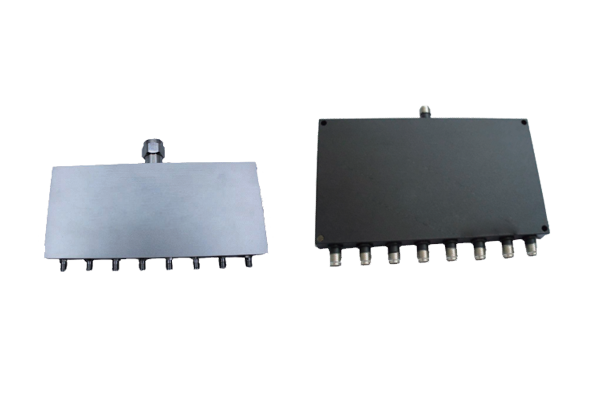
RF power dividers and power splitters are essential passive components in modern RF and microwave systems. They distribute an input signal across multiple output ports while maintaining the required impedance matching, signal balance, and isolation.
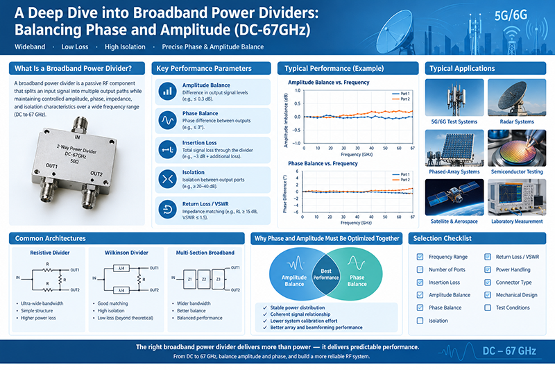
Broadband power dividers are fundamental RF and microwave components used to split an input signal into two or more output paths while maintaining predictable amplitude, phase, impedance, and isolation characteristics.
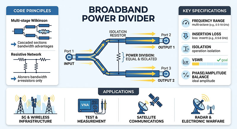
A Broadband Power Divider is an essential passive component designed to split an input signal into two or more output signals across a wide frequency range while maintaining impedance matching and minimal signal loss.
Power dividers are essential passive microwave components used in RF and communication systems to split one input signal into multiple output signals with controlled power distribution.
Jul 25 ,26
About the Author — MeiXun Team
Wang
Chief Engineer Wang
High-tech Enterprise, Feifeng Talent
Chief Engineer Wang graduated with a master's degree in high-power microwave from the Institute of Electronics, University of Chinese Academy of Sciences.
View Full Profile
Wang
Chief Engineer Wang
High-tech Enterprise, Feifeng Talent
Chief Engineer Wang graduated with a master's degree in high-power microwave from the Institute of Electronics, University of Chinese Academy of Sciences.
In the same year, he joined CETC 40/41 for work and study. He has been committed to the design and development of microwave switches for a long time.
He has applied for 27 patents as the first inventor in the microwave switch field, with 6 authorized invention patents and 14 utility model patents.
The products he developed cover various application platforms such as civilian testing, vehicle-mounted, shipborne, airborne, and missile-borne.