





1. What Is an RF Power Divider or Power Splitter?
An RF power divider is a passive microwave component that divides an input RF signal into two or more output signals. A power splitter generally performs the same function, and the two terms are often used interchangeably.
Common configurations include two-way, four-way, eight-way, unequal, wideband, and phase-controlled power dividers. The correct configuration depends on the operating frequency, number of signal paths, power requirements, and phase relationship.
2. How Does an RF Power Divider Work?
Input Signal Distribution
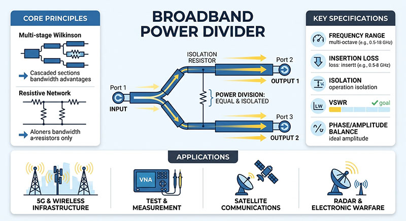
The input signal travels through an internal transmission-line, resistor, or coupled-circuit network that distributes energy among the output ports.
For an ideal equal two-way divider, each output receives half of the input power, corresponding to a theoretical division loss of approximately 3.01 dB per output. Practical devices introduce additional excess insertion loss.
Impedance Matching and Isolation
Most RF power dividers use a 50-ohm impedance, although 75-ohm versions are available. Proper impedance matching reduces reflections, while output isolation limits interaction between output channels.
Amplitude and Phase Balance
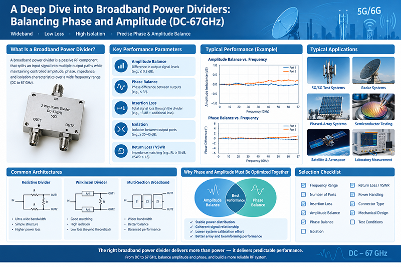
Amplitude balance describes the difference in output signal levels. Phase balance describes the difference between output phases relative to the intended phase relationship. Both are important in antenna arrays, coherent receivers, and beamforming networks.
3. Types of RF Power Dividers and Splitters
Wilkinson Power Divider
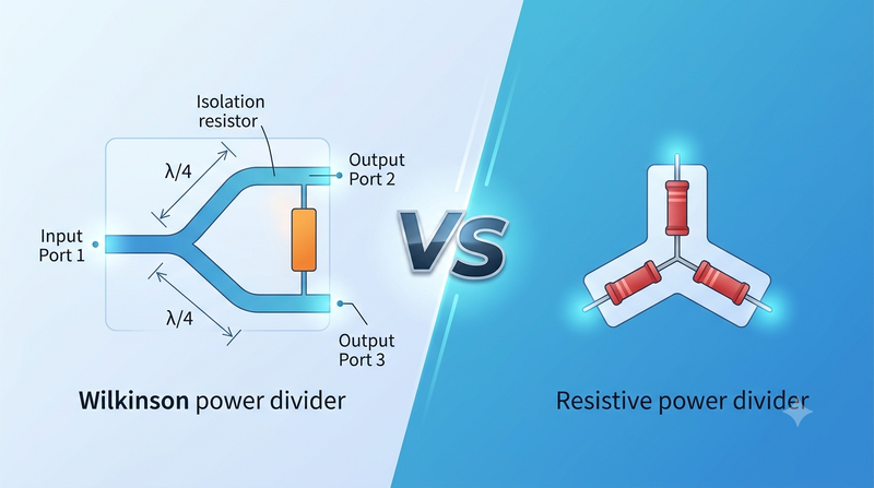
A Wilkinson power divider uses transmission-line sections and an isolation resistor to provide good impedance matching and output isolation. It is widely used in wireless communications, antenna arrays, RF transceivers, and microwave instrumentation. Conventional quarter-wave designs are frequency-dependent, while modified designs can extend bandwidth.
Resistive Power Divider
Resistive dividers offer simple construction, compact size, and potentially broad bandwidth. Their resistive elements dissipate power, resulting in greater insertion loss than an ideal lossless divider. They are often used for low-power signal distribution and laboratory measurements.
Hybrid Coupler-Based Divider
Hybrid couplers distribute RF power with defined phase relationships. Common examples include 90-degree quadrature hybrids and 180-degree hybrids. They are used in balanced amplifiers, antenna-feed networks, and beamforming circuits.
Unequal Power Divider
Unequal dividers distribute input power according to a specified ratio. They are suitable for antenna feeds, signal monitoring, and RF circuits that require different power levels at different output ports.
Wideband Power Divider
Wideband dividers operate over broad frequency ranges and are useful in spectrum monitoring, EMC testing, broadband communications, and laboratory instrumentation. Evaluate performance across the complete operating band.
Multi-Way Power Divider
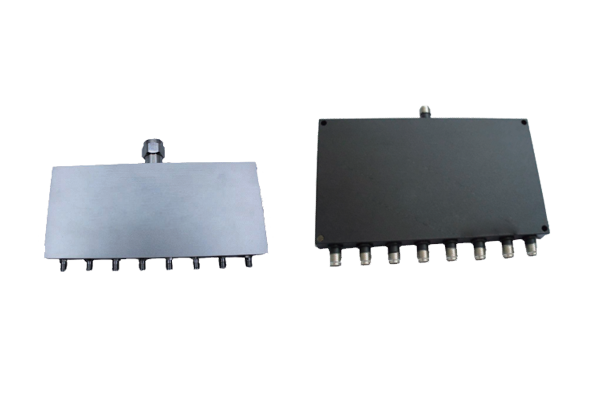
Multi-way dividers distribute a signal across four, eight, sixteen, or more outputs. They are common in phased-array antennas, radar systems, and multi-channel test equipment. An equal eight-way divider has a theoretical division loss of approximately 9.03 dB per output before excess losses.
4. RF Power Divider vs. Power Splitter
In most applications, RF power divider and power splitter describe the same general function. The actual circuit topology and performance specifications are more important than the product name.
| Type | Main Advantage | Typical Application |
|---|---|---|
| Wilkinson | Good isolation and low excess loss | RF communications and antenna arrays |
| Resistive | Simple structure and broad bandwidth | Low-power test systems |
| Hybrid coupler | Controlled phase relationship | Beamforming and balanced amplifiers |
| Unequal divider | Different output power levels | Signal distribution and monitoring |
| Multi-way divider | Multiple output channels | Radar and phased-array systems |
5. Key Specifications for Selecting an RF Power Divider
Operating Frequency Range
Confirm that the divider covers the entire required frequency band. A component's matching, insertion loss, and phase balance may vary with frequency.
Insertion Loss
Insertion loss includes the theoretical division loss and additional practical losses. For accurate system budgeting, verify the manufacturer's definition and measurement conditions.
Return Loss and VSWR
Higher return loss and lower VSWR generally indicate better impedance matching and reduced reflected power.
Amplitude and Phase Balance
Choose tolerances according to the requirements of the application. Tight balance is particularly important for phased-array antennas and coherent RF systems.
Output Isolation
Higher isolation reduces the interaction between output ports and can help limit the effect of load mismatch on other signal paths.
Power Handling
Check average power, peak power, duty cycle, ambient temperature, and mismatch conditions. Follow the manufacturer's operating limits and power-derating guidance.
Connectors and Mechanical Configuration
Verify connector type, impedance, gender, mounting style, package dimensions, and environmental requirements before installation.
6. How to Choose the Right RF Power Divider
- Define the frequency range: Include the complete operating band and any necessary guard band.
- Determine the output count: Select a two-way, four-way, eight-way, or other configuration.
- Specify the division ratio: Decide whether equal or unequal power distribution is required.
- Set balance requirements: Establish acceptable amplitude and phase errors.
- Define matching and isolation: Specify return loss, VSWR, and output isolation targets.
- Calculate the link budget: Include division loss, excess insertion loss, cables, connectors, and downstream requirements.
- Check operating conditions: Confirm power handling and environmental limits.
- Compare datasheets: Review performance curves and measured data across the intended band.
7. Applications of RF Power Dividers and Splitters
- Wireless communications: Distributing signals across antenna paths and transceiver channels.
- Phased-array antennas and radar: Maintaining specified amplitude and phase relationships across antenna elements.
- Satellite communications: Supporting microwave signal distribution and antenna-feed networks.
- RF testing and measurement: Feeding multiple instruments and measurement channels.
- RF amplifier systems: Distributing signals to parallel amplifier stages or supporting related combining architectures.
8. Common Selection Mistakes
- Selecting a divider based only on its center frequency.
- Ignoring excess insertion loss in the link budget.
- Confusing amplitude balance with phase balance.
- Overlooking output isolation requirements.
- Using a component outside its specified power limits.
- Assuming all splitters provide the same output phase relationship.
- Ignoring connector compatibility and impedance requirements.
9. Frequently Asked Questions
Is an RF power divider the same as an RF power splitter?
Usually, yes. Both terms commonly describe a component that distributes an RF input signal among multiple output ports. Check the datasheet for the actual design and specifications.
What is the theoretical loss of a two-way power divider?
An ideal equal two-way divider has a theoretical division loss of approximately 3.01 dB per output, excluding additional practical losses.
What is the difference between Wilkinson and resistive dividers?
Wilkinson dividers typically provide better output isolation and lower excess loss within their design bandwidth. Resistive dividers offer simple construction and broad bandwidth but dissipate more power.
Can an RF power divider be used as a combiner?
Many passive reciprocal divider networks can operate in reverse as combiners. However, source phase, amplitude, isolation, and port matching must be considered.
How do I select a divider for high-frequency applications?
Evaluate the full frequency range, insertion loss, return loss, isolation, phase balance, connector performance, and power rating. Measured S-parameter data can help validate performance.
Conclusion
RF power dividers and power splitters are fundamental components for distributing RF and microwave signals across multiple channels. The right selection depends on frequency, output count, division ratio, insertion loss, matching, isolation, phase balance, and power handling.
Wilkinson dividers are often suitable for applications requiring good isolation and low excess loss, while resistive dividers can be attractive when bandwidth and simplicity are priorities. Comparing complete datasheets and accounting for the RF link budget helps engineers select the right component for reliable system performance.