In Radio Frequency (RF) and microwave engineering, power splitters and dividers are fundamental passive components used to split an input signal into two or more output signals with specific phase and amplitude relationships. When engineering a system—whether for 5G telecommunications, radar systems, or laboratory test systems—engineers frequently face a choice: Wilkinson Power Divider vs. Resistive Power Divider.
Making the incorrect choice can lead to significant signal degradation, high insertion loss, port mismatch, or lack of port isolation. This comprehensive guide compares both topologies in detail to help you choose the right component for your specific RF application.
1. Understanding RF Power Dividers
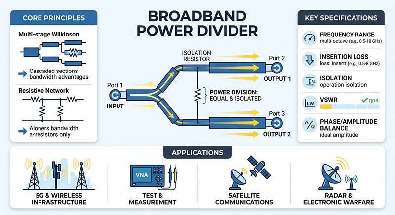
At a high level, an RF power divider takes a signal from an input port (Port 1) and splits it equally or unequally between multiple output ports (Port 2 and Port 3). Under ideal equal 2-way splitting, an RF power divider naturally delivers a 3 dB power reduction per port (50% power to each output branch), plus any inherent insertion losses caused by internal resistors or transmission line conductors.
2. Deep-Dive: Wilkinson Power Divider
Invented by Ernest J. Wilkinson in 1960, the Wilkinson power divider is an isolation-matched power splitter topology widely utilized in narrow-to-moderate bandwidth microwave circuits.
Topology and Design
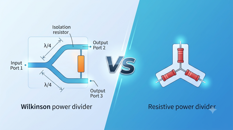
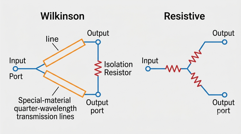
A standard 2-way Wilkinson power divider utilizes quarter-wavelength (λ/4) transmission lines with a characteristic impedance of √2 × Z0 (approximately 70.7 Ω in a standard 50 Ω system). A single isolation resistor of 2 × Z0 (100 Ω) is connected across the two output ports.
Key Advantages of Wilkinson Power Dividers
- High Output Port Isolation: The isolation resistor absorbs reflected signals coming back into the output ports, preventing crosstalk between Port 2 and Port 3. Isolation levels typically exceed 20 dB to 25 dB at the center frequency.
- Low Insertion Loss: Because the internal isolation resistor carries virtually no current when output ports are perfectly matched, electrical signal dissipation is minimal. Typical loss above the 3 dB split is less than 0.2–0.5 dB.
- All Ports Matched (Low VSWR): All three ports are theoretically matched to 50 Ω at the operating frequency, offering superior Return Loss performance.
- Reciprocal Behavior: A Wilkinson divider functions equally well as a low-loss power combiner when signals applied to the output ports are in phase and equal in amplitude.
Limitations
- Bandwidth Constraints: Standard single-stage Wilkinson dividers rely on quarter-wave (λ/4) microstrip lines, limiting their optimal performance bandwidth to roughly 15–20% around the center frequency (though multi-stage topologies can extend this).
- Physical Size at Low Frequencies: Because line length scales inversely with frequency, Wilkinson dividers become physically large at lower frequencies (e.g., sub-100 MHz).
- No DC Response: Standard quarter-wave lines act as open or reactive networks to DC, making Wilkinson splitters unsuitable for DC-coupled applications without bias tees.
3. Deep-Dive: Resistive Power Divider
Resistive power dividers are simple, highly compact passive components constructed purely with lump-element surface-mount or thin-film resistors arranged in a star or delta configuration.
Topology and Design
A standard 2-resistor power divider (often called a power splitter) or 3-resistor equal power divider uses precise resistive elements (e.g., 16.67 Ω resistors in a 3-resistor star layout, or 50 Ω in a 2-resistor layout) to achieve impedance matching without employing transmission lines.
Key Advantages of Resistive Power Dividers
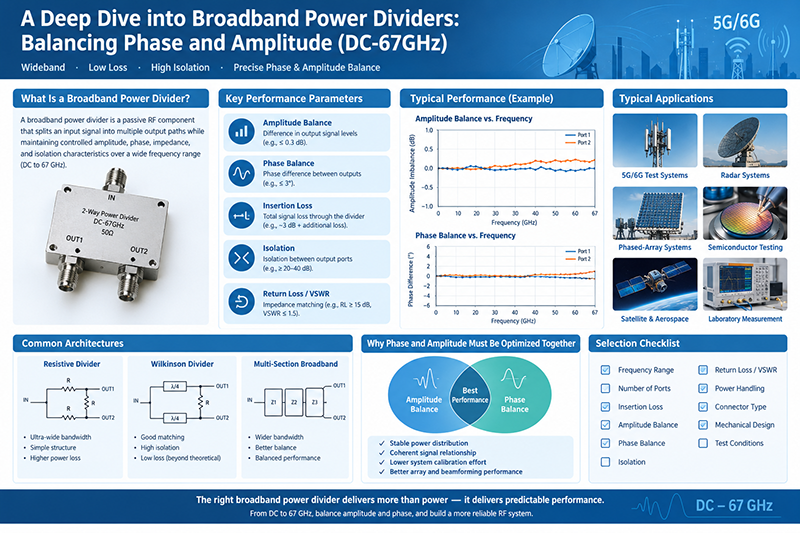
- Extremely Wide Bandwidth (DC to Ultra-High RF): Unbound by wavelength-dependent transmission lines, resistive dividers operate seamlessly from DC (0 Hz) up to tens of Gigahertz (e.g., 40 GHz+).
- Compact Form Factor: Because they rely solely on SMD or thin-film resistors, resistive dividers occupy minimal PCB real estate.
- Phase & Amplitude Flatness: Exceptional amplitude tracking and phase balance across ultra-broad frequency ranges.
Limitations
- High Insertion Loss: In a 3-resistor power divider, the insertion loss is 6 dB (3 dB theoretical power split + 3 dB resistive dissipation loss), meaning 50% of the input signal power is converted into heat inside the resistors.
- Poor Output Isolation: Resistive splitters offer low isolation between output ports (typically only 6 dB). A signal reflected into Port 2 will easily couple into Port 3.
- Low Power Handling: High insertion loss translates directly to internal heat generation, limiting power handling to low-signal applications (typically < 1 Watt).
4. Head-to-Head Comparison Table
| Feature / Parameter | Wilkinson Power Divider | Resistive Power Divider |
|---|---|---|
| Frequency Range | Narrow to Multi-Octave (Frequency Dependent) | Ultra-Broadband (DC to 40 GHz+) |
| Insertion Loss (above 3 dB split) | Low (< 0.5 dB typical) | High (3.0 dB internal loss = 6 dB total) |
| Port Isolation (Port 2 to Port 3) | High (> 20 dB at resonance) | Low (~ 6 dB) |
| Port Matching (VSWR) | Excellent at center frequency | Good across entire bandwidth |
| DC Pass Capability | No (unless specialized layout) | Yes (Full DC pass-through) |
| Power Handling Capacity | Moderate to High (Watts to tens of Watts) | Low (< 1 Watt typical) |
| Physical Dimensions | Larger (λ/4 lines required) | Extremely Compact (Lumped Resistors) |
| Power Combining Suitability | Excellent (In-phase combining) | Poor (Significant power lost as heat) |
5. Key Selection Criteria: How to Decide
To determine the best fit for your design, evaluate your RF system requirements against these critical engineering dimensions:
A. Signal Loss and System Link Budget
If your system budget cannot tolerate a extra 3 dB signal penalty (such as in transmitter front-ends or low-noise receiver paths), a Wilkinson divider is required. Its low insertion loss preserves signal-to-noise ratio (SNR) and efficiency.
B. Crosstalk and Isolation Requirements
In antenna array feed networks or multi-channel transceivers, reflections from one antenna branch must not interfere with adjacent channels. The Wilkinson divider's isolation resistor isolates ports by dissipating differential signals, making it the preferred choice.
C. Frequency Spectrum & Bandwidth Requirements
If your design spans from DC up to millimeter-wave frequencies (e.g., broadband test systems, oscilloscope probes, measurement setups), a resistive divider is often the only passive solution capable of handling such bandwidth seamlessly.
D. Circuit Board Real Estate
For space-constrained PCB layouts operating below 1 GHz where quarter-wave microstrip traces consume excessive area, resistive power dividers or multi-layer lumped-element Wilkinson components offer practical footprints.
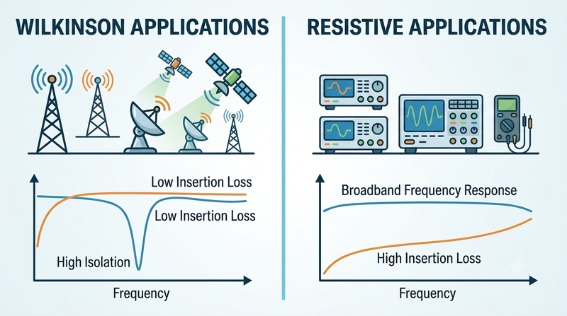
6. Typical Applications Summary
-
Wilkinson Applications:
- Phase-array antenna feeds and beamforming networks
- RF power amplifiers (combining output stages)
- Cellular base stations (LTE, 5G NR sub-6 GHz)
- Low-noise receiving systems requiring high isolation
-
Resistive Applications:
- RF calibration setups and leveling loops
- Ultra-broadband lab test instrumentation
- DC-biased RF measurement circuits
- Precision signal sampling and audio/RF monitoring
Frequently Asked Questions (FAQ)
Conclusion
Choosing between a Wilkinson and a Resistive RF power divider comes down to trade-offs between bandwidth, insertion loss, and isolation. Wilkinson dividers lead in low loss, high isolation, and efficiency for narrowband or multi-band wireless communications. Conversely, Resistive dividers deliver unmatched broadband performance from DC to UHF/SHF microwave frequencies where compact size and ultra-broadband response outweigh power loss considerations.