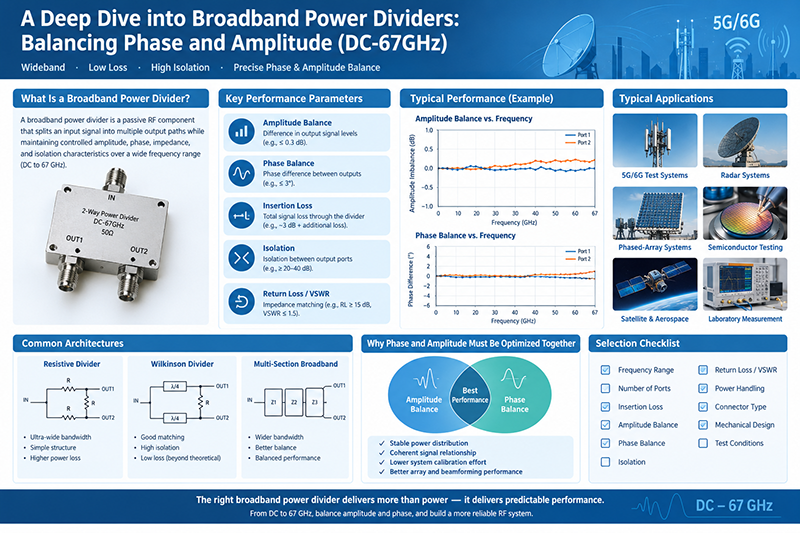
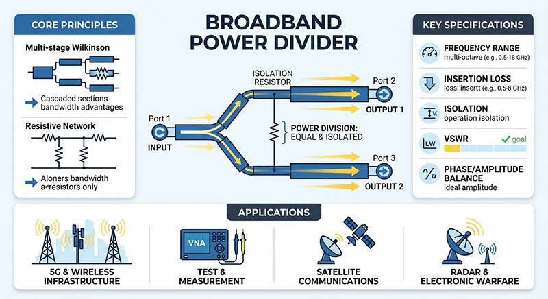
Power dividers are essential passive microwave components used in RF and communication systems to split one input signal into multiple output signals with controlled power distribution. They are widely used in wireless communication, radar systems, satellite communication, test equipment, and antenna networks.
A high-performance power divider provides excellent signal balance, low insertion loss, high isolation, and stable operation across a wide frequency range. Understanding different types of power dividers and their specifications is critical for selecting the right component for RF applications.
Key Takeaway: Power dividers enable efficient signal distribution in RF systems by dividing input power into two or more output paths while maintaining signal integrity and phase consistency.
What Is a Power Divider?

A power divider is a passive RF device that divides an incoming microwave signal into multiple output signals. Unlike simple electrical splitters, professional RF power dividers are designed to maintain impedance matching, minimize signal loss, and provide consistent phase and amplitude characteristics.
Most power dividers use a 50-ohm impedance design to match standard RF transmission systems. They can divide signals equally or unequally depending on system requirements.
How Does a Power Divider Work?
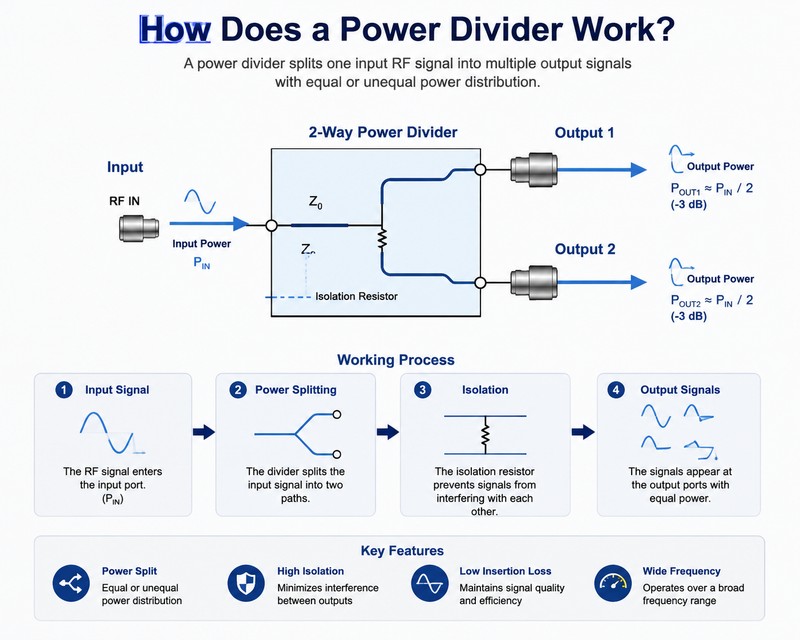
A power divider operates based on transmission line theory and microwave circuit design. When an RF signal enters the input port, the device distributes the signal energy across multiple output ports.
Basic Operating Principle
-
The input RF signal enters the common port.
-
The internal circuit divides the signal power into multiple paths.
-
Each output port receives a controlled portion of the input signal.
-
Isolation between output ports reduces signal interference.
For example, a 2-way equal power divider ideally provides each output with half of the input power, resulting in approximately 3 dB theoretical power loss per output port.
Types of Power Dividers
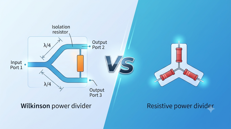
1. Wilkinson Power Divider
Wilkinson power dividers are among the most widely used RF power distribution devices. They provide excellent isolation between output ports while maintaining low insertion loss.
-
Low insertion loss
-
High output port isolation
-
Excellent amplitude balance
-
Good phase performance
Wilkinson designs are commonly used in cellular base stations, phased array antennas, and microwave test systems.
2. Resistive Power Divider
Resistive power dividers use resistor networks to split RF signals. They offer broadband operation but have higher insertion loss compared with Wilkinson designs.
-
Simple structure
-
Wide frequency bandwidth
-
Lower cost
-
Higher power loss
3. Hybrid Power Divider
Hybrid power dividers use microwave hybrid coupler technology to provide precise phase relationships between output signals.
-
Excellent phase control
-
High isolation
-
Suitable for advanced RF systems
4. Unequal Power Divider
Unequal power dividers distribute different power levels to each output port. They are used when RF systems require customized signal allocation.
Common Power Divider Configurations
|
Configuration
|
Description
|
Applications
|
|
2-Way Power Divider
|
Splits one input into two outputs
|
Antenna systems, RF testing
|
|
4-Way Power Divider
|
Divides signals into four channels
|
Wireless networks, phased arrays
|
|
8-Way Power Divider
|
Provides multiple output distribution
|
Radar and communication systems
|
|
Multi-Way Power Divider
|
Custom output configurations
|
Complex microwave systems
|
Important Specifications of Power Dividers
Insertion Loss
Insertion loss represents the amount of signal power lost when passing through the divider. Lower insertion loss improves system efficiency and signal quality.
Isolation
Isolation indicates how well output ports are separated from each other. Higher isolation reduces interference between channels.
Frequency Range
The operating frequency range determines whether the power divider is suitable for specific RF applications. Common frequency bands include DC-6GHz, 18GHz, 40GHz, and higher microwave frequencies.
Power Handling Capability
RF power dividers must handle the required input power without overheating or performance degradation. High-power applications require specially designed components.
VSWR
Low VSWR ensures good impedance matching and minimizes signal reflection within the RF system.
Applications of Power Dividers
-
Wireless Communication: Used in base stations, distributed antenna systems, and 5G networks.
-
Radar Systems: Provides signal distribution for phased array antennas.
-
Satellite Communication: Enables reliable RF signal routing.
-
RF Testing: Used in laboratory measurement systems and network analyzers.
-
Military and Aerospace: Supports advanced microwave communication systems.
-
Antenna Arrays: Ensures balanced signal feeding across multiple antenna elements.
Power Divider vs Power Combiner
A power divider and power combiner are essentially reciprocal devices. A divider splits one signal into multiple outputs, while a combiner combines multiple signals into one output.
|
Feature
|
Power Divider
|
Power Combiner
|
|
Signal Direction
|
One input to multiple outputs
|
Multiple inputs to one output
|
|
Main Function
|
Signal distribution
|
Signal combining
|
|
Typical Use
|
Antenna networks
|
Power amplification systems
|
How to Choose the Right Power Divider
Selecting the correct power divider requires evaluating several key parameters:
-
Operating frequency range
-
Number of output ports
-
Required power handling capability
-
Insertion loss requirements
-
Isolation requirements
-
Phase and amplitude balance
-
Connector type and mechanical design
Why Choose High-Quality RF Power Dividers?
High-quality power dividers improve system reliability by providing stable electrical performance, accurate signal distribution, and long-term durability. Professional RF manufacturers use precision machining and advanced testing equipment to ensure consistent performance across demanding applications.
Frequently Asked Questions About Power Dividers
What is the purpose of a power divider?
A power divider distributes an RF input signal into multiple output signals while maintaining controlled power levels and signal quality.
What is the difference between a splitter and a power divider?
A basic splitter is usually designed for general electrical signal distribution, while an RF power divider provides controlled impedance matching, isolation, and microwave performance.
How much power loss does a 2-way power divider have?
An ideal 2-way power divider has approximately 3 dB theoretical power reduction at each output, excluding additional insertion loss.
Conclusion
Power dividers are fundamental components in modern RF and microwave systems. From wireless communication and radar to satellite links and laboratory testing, they provide reliable signal distribution with precise control of power, phase, and isolation.
Choosing the right power divider requires careful consideration of frequency range, insertion loss, isolation, power capacity, and application requirements. A properly selected RF power divider can significantly improve overall system performance and reliability.