

























What is an N-type connector? Learn about the N-type coaxial RF connector — its origin, mechanical design, electrical performance, common variants, and applications up to 18 GHz.
Sep 09 ,26


5G communication testing, wireless terminal automated testing
Aerospace communication systems
Precision measurement equipment, radio frequency signal control of radar transmitters
Communication and navigation systems
Optical communication module-related testing
Interconnection of wireless communication base stations
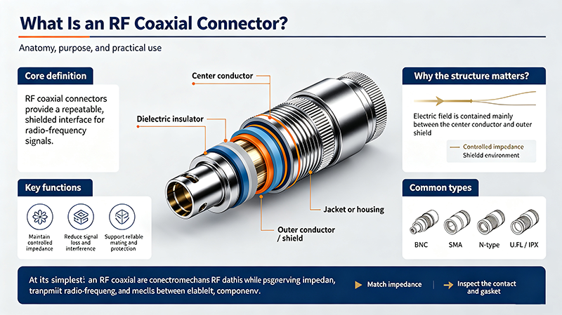
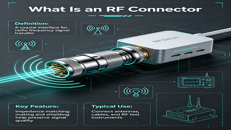
An RF coaxial connector is a precision electrical component designed to transmit radio frequency signals with minimal loss and reflection between coaxial cables, equipment, and antennas. It maintains the characteristic impedance of the transmission line, typically 50 ohms for communications and 75 ohms for video and broadcast, while shielding signals from external electromagnetic interference.
Choosing the correct RF connector is critical for system performance, signal integrity, mechanical durability, and long-term reliability. A mismatched connector can introduce VSWR problems, power loss, and intermittent connections in the field.
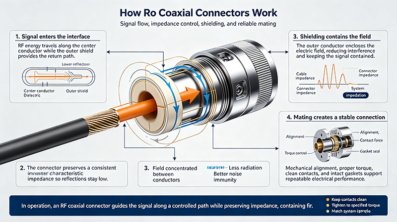
RF coaxial connectors use a center contact and an outer shield contact separated by a dielectric insulator. When mated, the center pins align to carry the signal while the outer conductors form the return circuit and the electromagnetic shield. Precision machining ensures consistent impedance and stable contact resistance across thousands of mating cycles.
The chart below compares the most common RF coaxial connector families used in modern electronics and communications systems.
| Type | Impedance | Frequency Range | Coupling Style | Typical Application |
|---|---|---|---|---|
| SMA | 50 Ω | DC – 18 GHz (up to 26.5 GHz) | Threaded | Wi-Fi, GPS, test equipment, microwave |
| BNC | 50 Ω / 75 Ω | DC – 4 GHz | Bayonet | Lab instruments, video, oscilloscopes |
| TNC | 50 Ω | DC – 11 GHz | Threaded | Vibration-prone, mobile, military radio |
| N-Type | 50 Ω | DC – 11 GHz (up to 18 GHz) | Threaded | Base stations, antennas, radar |
| SMB | 50 Ω | DC – 4 GHz | Snap-on | Telecom boards, quick mating |
| SMC | 50 Ω | DC – 10 GHz | Threaded | Compact RF modules, aerospace |
| MCX | 50 Ω | DC – 6 GHz | Snap-on | GPS, GNSS, small consumer devices |
| F-Type | 75 Ω | DC – 1 GHz | Threaded | Cable TV, satellite, broadband |
| UHF / PL-259 | 50 Ω (non-constant) | DC – 300 MHz | Threaded | CB radio, amateur HF/VHF |
| 2.92 mm (K) | 50 Ω | DC – 40 GHz | Threaded | mmWave test, 5G, radar |
| 2.4 mm | 50 Ω | DC – 50 GHz | Threaded | Lab-grade microwave test |
| 1.85 mm (V) | 50 Ω | DC – 67 GHz | Threaded | High-frequency instrumentation |
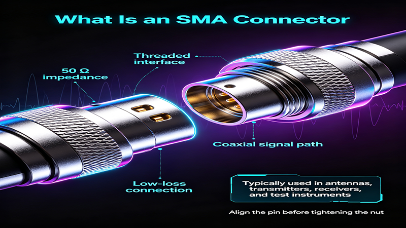
The SubMiniature version A connector is one of the most widely used RF connectors. With a 50 ohm impedance and excellent performance up to 18 GHz, it is the standard for Wi-Fi modules, GPS antennas, cellular boosters, RF test instruments, and microwave subsystems. SMA connectors use a 1/4-inch hex nut threaded coupling and offer hundreds of reliable mating cycles.
The Bayonet Neill-Concelman connector is popular in laboratories, broadcast studios, and test equipment because of its quick quarter-turn bayonet locking mechanism. Available in both 50 ohm and 75 ohm versions, BNC connectors operate reliably up to 4 GHz and remain the default on most oscilloscopes and signal generators.
The Threaded Neill-Concelman connector is essentially a threaded BNC. The screw-on coupling makes it ideal for environments with vibration, shock, or repeated movement, such as mobile radio, military communications, and outdoor antennas operating up to 11 GHz.
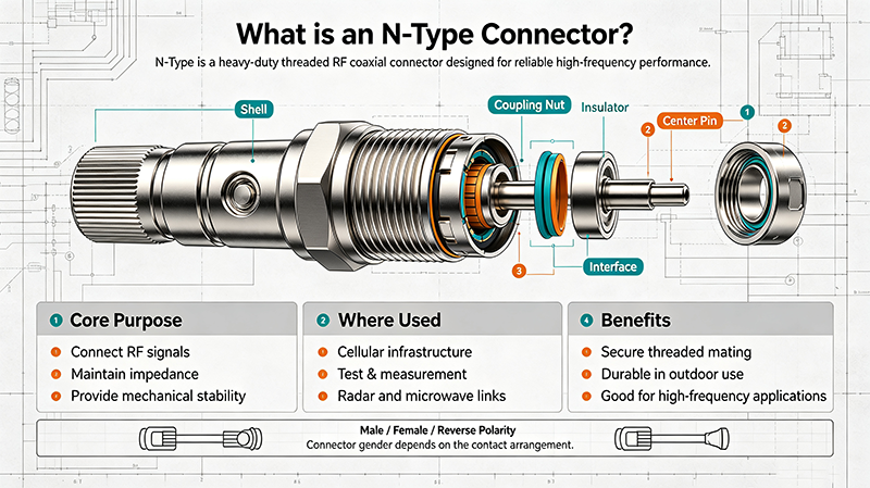
Designed for heavier cables and higher power applications, the N-Type connector is a threaded, weather-resistant RF connector widely used in cellular base stations, broadcast transmitters, radar systems, and outdoor antenna installations. Its rugged construction supports frequencies up to 11 GHz and beyond.
SMB (Snap-on) and SMC (Screw-on) are miniature 50 ohm connectors designed for internal equipment wiring where space is limited. SMB offers quick push-on mating up to 4 GHz, while SMC provides a threaded version for more secure connections up to 10 GHz. Both are common in telecom PCBs and RF modules.
MCX and MMCX connectors are micro-miniature 50 ohm designs used where board space and weight matter. MCX provides snap-on mating up to 6 GHz, while MMCX offers a smaller footprint with similar performance. They are standard on GPS receivers, GNSS modules, and compact wireless devices.
The F-Type is a 75 ohm screw-on connector that dominates residential broadband, cable television, satellite receivers, and set-top boxes. Low cost and easy installation make it the universal choice for consumer video and DOCSIS modem connections.
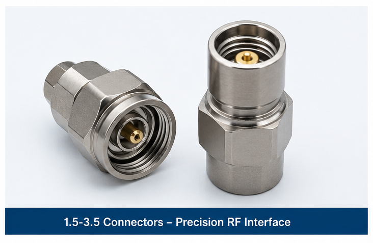
For millimeter-wave and high-frequency test, precision air-dielectric connectors such as 2.92 mm (K), 2.4 mm, and 1.85 mm (V) deliver accurate measurements up to 40 GHz, 50 GHz, and 67 GHz respectively. They are essential in vector network analyzers, RF test racks, and 5G product development.
Choosing the best RF connector requires balancing electrical performance, mechanical constraints, and environmental conditions. Use the checklist below as a starting point.
SMA, N-Type and 4.3-10 connectors power 4G and 5G base stations, small cells, and DAS networks.
BNC, SMA, and precision 2.4 mm/2.92 mm connectors interface with VNAs, spectrum analyzers and oscilloscopes.
TNC, N-Type and TNC-sealed connectors meet MIL-STD requirements for radar, avionics and tactical radios.
BNC 75 ohm and F-Type connectors carry SDI, HD video, satellite IF and broadband signals.
MCX, MMCX and U.FL connectors link GNSS, Wi-Fi and Bluetooth modules inside compact devices.
Sealed N-Type and SMA connectors support RFID, MRI coils, and industrial wireless sensors.
50 ohm connectors are optimized for RF power and data communications, while 75 ohm versions are tuned for video and broadband. They are not interchangeable; mismatched impedance causes signal reflection and degraded performance.
No. SMA has a male center pin and female socket; RP-SMA reverses that polarity. They look similar but are mechanically and electrically incompatible. Confirm polarity before ordering antennas and pigtails.
N-Type with weatherproof sealing and stainless steel hardware is the most common outdoor choice. For low-frequency video, weatherproof F-Type connectors are also widely used.
Standard SMA and N-Type connectors are typically rated for 500 mating cycles. Precision test connectors (2.4 mm, 2.92 mm) often reach 500 to 1000 cycles when properly handled.
VSWR (Voltage Standing Wave Ratio) measures how efficiently RF power is transmitted through the connector. Lower VSWR — closer to 1:1 — indicates better impedance matching and less reflected signal.
Selecting the right RF coaxial connector is foundational to any reliable high-frequency system. By matching impedance, frequency range, mechanical coupling and environmental protection to your application, you maximize signal integrity, reduce maintenance, and extend product life. Use the types chart and selection guide above as a quick reference whenever you evaluate SMA, BNC, N-Type, TNC or precision millimeter-wave connectors for your next design.

High-tech Enterprise, Feifeng Talent
Chief Engineer Wang graduated with a master's degree in high-power microwave from the Institute of Electronics, University of Chinese Academy of Sciences.
View Full Profile