


























RF connectors are critical interfaces in microwave, wireless communication, radar, test and measurement,
satellite, and high-freque...
Sep 08 ,26


5G communication testing, wireless terminal automated testing
Aerospace communication systems
Precision measurement equipment, radio frequency signal control of radar transmitters
Communication and navigation systems
Optical communication module-related testing
Interconnection of wireless communication base stations
RF connectors are essential components used to transmit radio frequency signals between cables, devices, antennas, test equipment, and communication systems. From wireless communication and radar to satellite systems and high-frequency laboratory testing, the right RF connector helps maintain signal integrity and reliable electrical performance.
In this guide, you will learn what an RF connector is, how it works, the different types of RF connectors, their applications, and how to choose the right connector for your RF or microwave system.
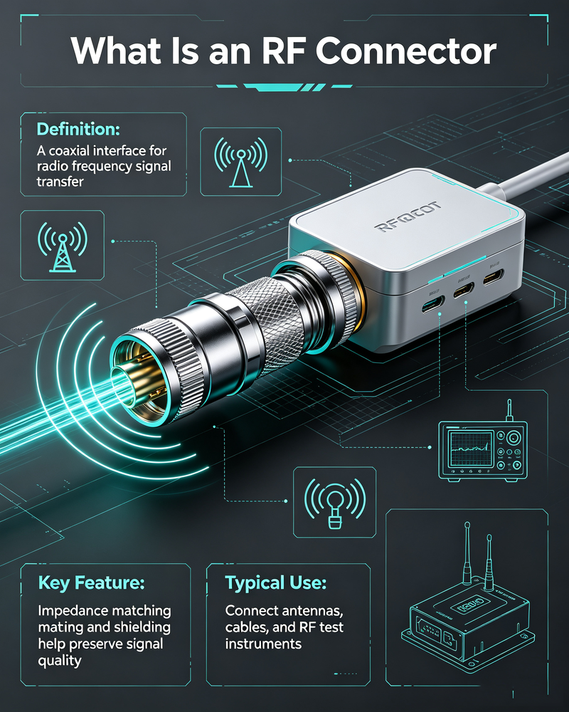
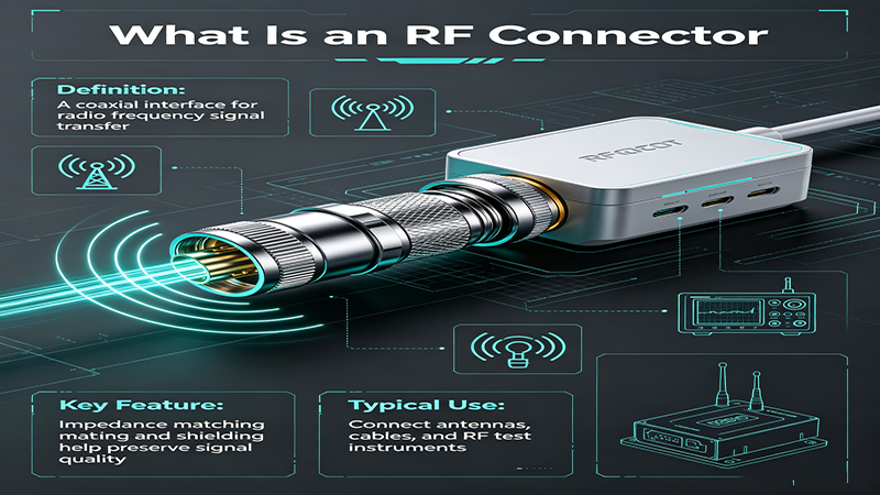
An RF connector, also known as a radio frequency connector, is an electrical connector specifically designed to connect and disconnect RF and microwave transmission lines. It is commonly used with coaxial cables and RF devices operating from low frequencies up to microwave and millimeter-wave frequency ranges.
Unlike ordinary electrical connectors, RF connectors are designed to maintain a controlled impedance, minimize signal reflection, reduce insertion loss, and provide reliable shielding against electromagnetic interference.
Most RF connectors are based on a coaxial structure. They contain a center conductor surrounded by a dielectric material and an outer conductor. This structure helps maintain the characteristic impedance of the transmission path, typically 50 ohms or 75 ohms.
In simple terms: An RF connector provides a controlled connection between two RF components while helping preserve the quality and integrity of the transmitted high-frequency signal.
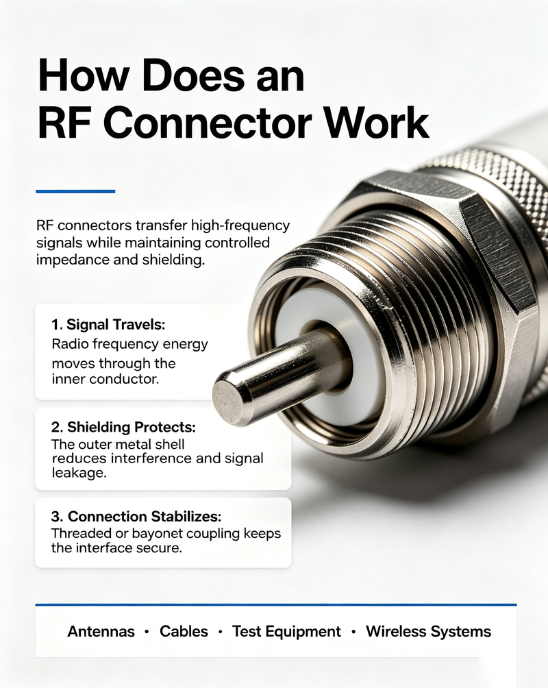
An RF connector works by extending the coaxial transmission line from one component to another. When properly connected, the center conductor carries the RF signal while the outer conductor provides the return path and electromagnetic shielding.
The connector must maintain consistent electrical geometry throughout the connection. Even small dimensional changes can create an impedance discontinuity, causing part of the RF signal to be reflected back toward the source.
A properly designed RF connector helps achieve:
For example, if a 50-ohm coaxial cable is connected to a 50-ohm RF device using a properly matched connector, the RF energy can transfer efficiently through the connection. If the impedance changes significantly, the resulting mismatch can increase VSWR and reduce overall system performance.
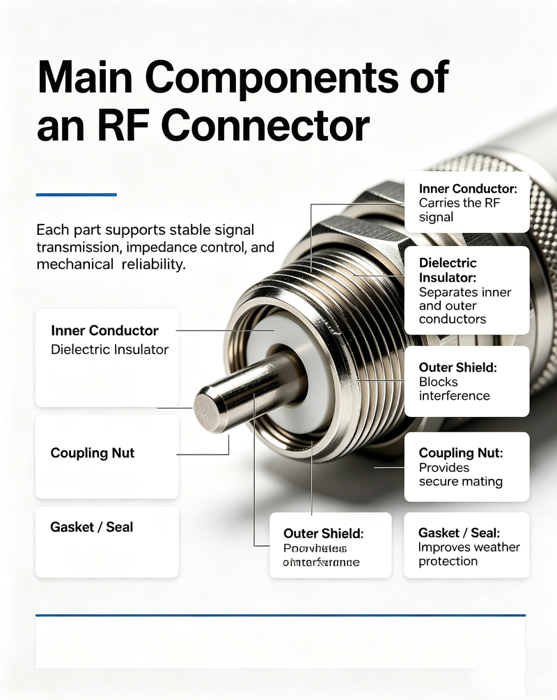
Although RF connectors vary in size and design, most coaxial RF connectors include several basic components.
The center contact carries the RF signal and connects the inner conductors of two transmission lines or devices.
The dielectric material electrically isolates the center conductor from the outer conductor and helps maintain the connector's impedance.
The outer conductor provides the return path for the signal and shields the transmission line from external electromagnetic interference.
Threaded, bayonet, push-on, snap-on, and other coupling mechanisms provide mechanical connection between mating RF connectors.
The connector body provides mechanical strength and protects the internal electrical components.
The cable interface may use crimp, clamp, solder, compression, or other termination methods depending on the connector type.
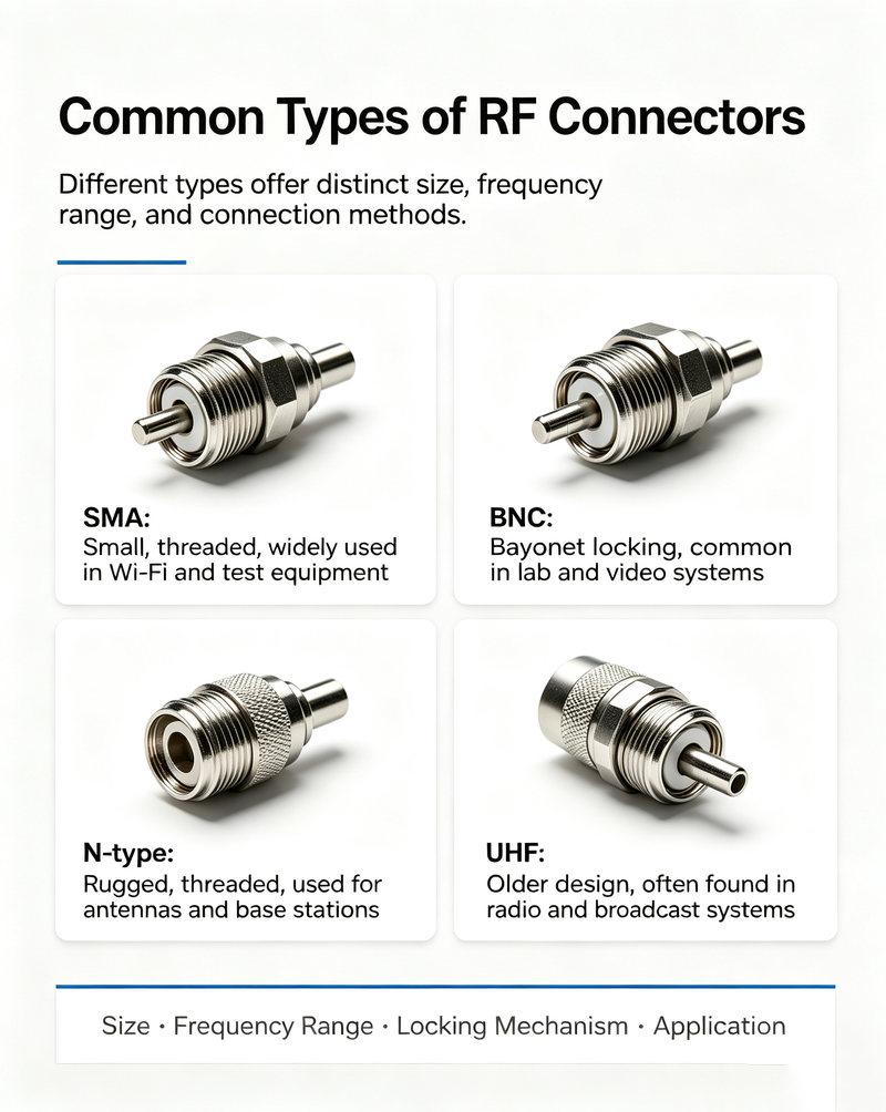
There are many RF connector types designed for different frequency ranges, power levels, cable sizes, environmental conditions, and applications. Below are some of the most common types.
The SMA connector is one of the most widely used RF and microwave connectors. It uses a threaded coupling mechanism and is commonly designed for 50-ohm systems.
SMA connectors are popular in test equipment, antennas, RF modules, microwave circuits, wireless communication systems, and laboratory applications. Standard SMA connectors are typically used up to 18 GHz, while precision and high-performance versions can support higher frequencies.
The N-type connector is a durable threaded RF connector commonly used in outdoor and high-power applications. It is available in 50-ohm and 75-ohm versions.
N-type connectors are widely used in base stations, antennas, wireless infrastructure, radar systems, broadcast equipment, and outdoor communication installations.
The BNC connector uses a bayonet-style coupling mechanism that allows quick connection and disconnection. It is commonly used in laboratory instruments, video systems, test equipment, and lower-frequency RF applications.
BNC connectors are available in both 50-ohm and 75-ohm configurations, so impedance compatibility should always be checked before use.
The TNC connector is similar in structure to a BNC connector but uses a threaded coupling mechanism. The threaded connection provides improved mechanical stability and better performance in applications involving vibration.
TNC connectors are commonly used in wireless communication, antennas, military equipment, and industrial RF systems.
UHF connectors, often associated with PL-259 and SO-239 interfaces, are widely used in lower-frequency radio applications. They are common in amateur radio, CB radio, and some communication systems.
However, UHF connectors are generally not preferred for modern high-frequency microwave applications because their impedance characteristics are less controlled than precision RF connectors.
MCX and MMCX connectors are compact RF connectors designed for applications where space is limited. Their small size makes them suitable for GPS devices, wireless modules, compact communication equipment, and PCB-mounted RF products.
These precision RF connectors are designed for high-frequency microwave and millimeter-wave applications.
They are widely used in high-frequency test systems, vector network analyzers, semiconductor testing, radar, satellite communication, and advanced microwave research.
The 3.5 mm connector is a precision microwave connector commonly used in laboratory and test applications. It offers excellent electrical performance and is widely used in high-quality measurement systems.
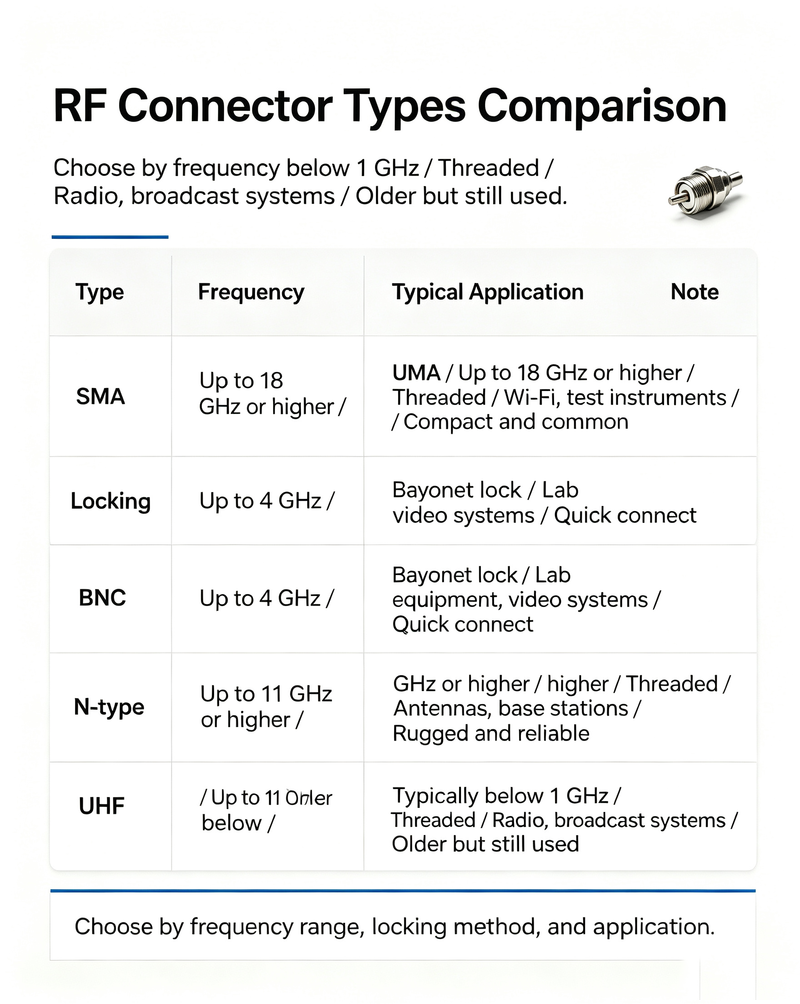
| Connector Type | Typical Impedance | Typical Frequency Range | Coupling Type | Common Applications |
|---|---|---|---|---|
| SMA | 50 Ohm | Up to 18 GHz or higher | Threaded | RF modules, antennas, test equipment |
| N-Type | 50 / 75 Ohm | Up to approximately 11 GHz or higher | Threaded | Base stations, antennas, outdoor systems |
| BNC | 50 / 75 Ohm | Low to medium frequency RF | Bayonet | Test equipment, video, instrumentation |
| TNC | 50 Ohm | Up to approximately 11 GHz or higher | Threaded | Wireless and vibration-resistant applications |
| MCX | 50 Ohm | Up to approximately 6 GHz | Snap-On | Compact RF equipment and GPS |
| MMCX | 50 Ohm | Up to approximately 6 GHz | Snap-On | Miniature RF modules |
| 2.92 mm | 50 Ohm | Up to 40 GHz | Threaded | Microwave testing and radar |
| 1.85 mm | 50 Ohm | Up to 67 GHz | Threaded | Millimeter-wave and precision testing |
RF connectors are commonly described as male or female, although the exact contact design can vary depending on the connector family.
Traditionally:
However, some precision RF connector systems use different gender conventions, such as reverse-polarity connectors. Therefore, it is important to verify the complete connector specification rather than relying only on a general male or female description.
When selecting an RF connector, engineers should consider several important electrical and mechanical specifications.
The connector must support the highest frequency used by the system. Using a connector beyond its rated frequency range can result in poor return loss, increased insertion loss, and unstable performance.
The most common RF connector impedances are 50 ohms and 75 ohms. The connector should match the impedance of the cable and connected equipment whenever possible.
VSWR and return loss indicate how well the connector is impedance matched. A lower VSWR and higher return loss generally indicate better RF performance.
Insertion loss measures the amount of signal power lost as the RF signal passes through the connector. Low insertion loss is particularly important in high-frequency and low-power systems.
RF connectors have maximum power ratings that depend on frequency, connector design, materials, voltage limits, and operating conditions. High-power transmitters require connectors capable of handling the required RF power safely.
Threaded connectors generally provide strong mechanical connections, while push-on or snap-on connectors offer faster installation. The best choice depends on the application.
Outdoor and harsh-environment applications may require RF connectors with improved resistance to moisture, dust, vibration, temperature changes, corrosion, and repeated mating cycles.
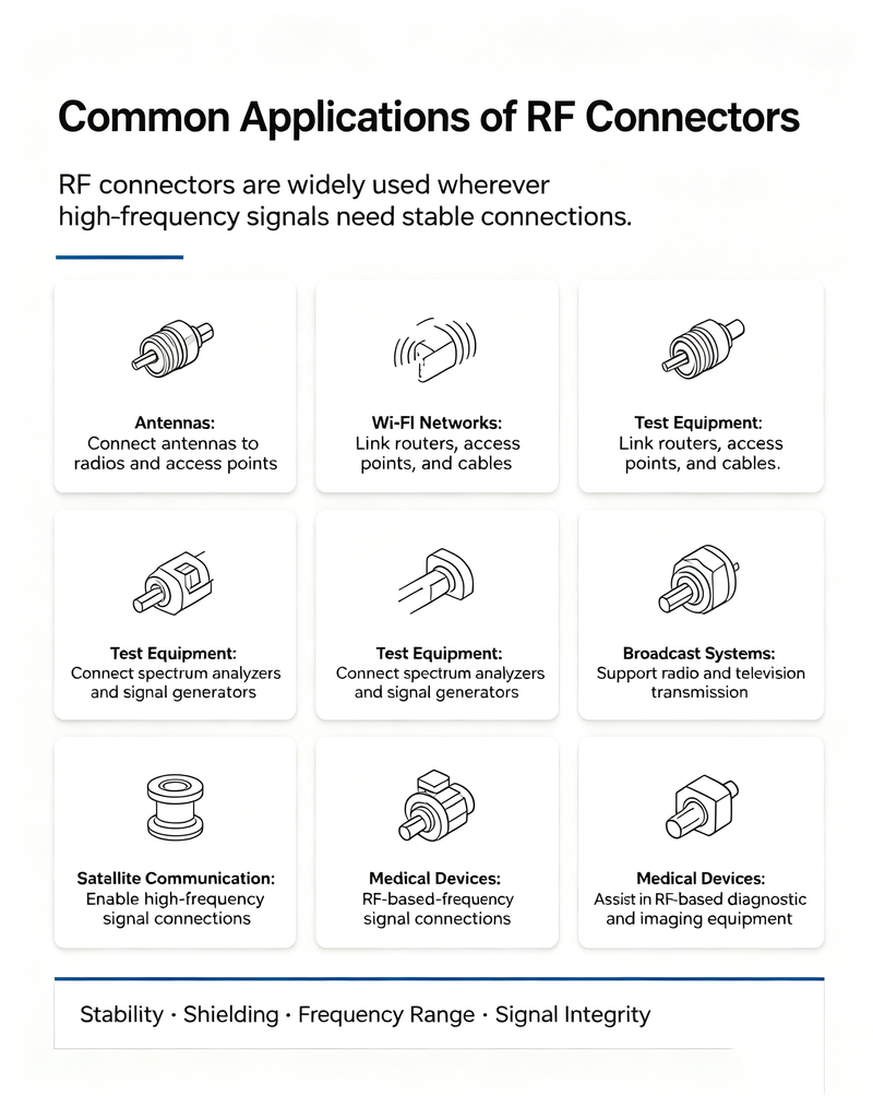
RF connectors are used in a wide range of industries and electronic systems, including:
Selecting the right RF connector requires more than simply choosing a connector that physically fits the cable. Electrical performance, frequency, power, environment, and mechanical requirements must all be considered.
Start by identifying the maximum operating frequency of your RF system. Choose a connector rated above the highest frequency you expect to use.
For most RF and microwave systems, 50-ohm connectors are standard. For certain video and broadcast applications, 75-ohm connectors may be required.
The connector must be compatible with the type and diameter of the coaxial cable. Different cables require different connector designs and termination methods.
High-power RF systems require connectors with adequate voltage and power-handling capability.
For outdoor installations, consider waterproofing, corrosion resistance, UV exposure, temperature range, and vibration resistance.
Laboratory and test environments may require connectors that can withstand frequent connection and disconnection. Precision connectors should also be handled carefully to avoid damage to the mating surfaces.
Compare key specifications such as VSWR, return loss, insertion loss, and frequency range. High-frequency measurement applications often require precision-grade RF connectors.
Selection Tip: The best RF connector is not necessarily the smallest or highest-frequency connector. Choose the connector that provides the required electrical performance, mechanical reliability, environmental protection, and cost efficiency for your specific application.
Even a high-quality RF connector can perform poorly if it is incorrectly installed or damaged. Proper installation and maintenance are essential for maintaining reliable RF performance.
At low frequencies, a simple electrical connection may have little effect on overall system performance. At RF and microwave frequencies, however, every connection becomes part of the transmission line.
A poorly selected or improperly installed RF connector can cause:
For high-performance systems operating at microwave and millimeter-wave frequencies, connector quality and interface precision can have a significant impact on the overall performance of the RF signal path.
An RF connector is designed to terminate a cable or provide a direct RF interface on a device. An RF adapter is used to connect two different connector interfaces or extend an RF connection.
For example, an SMA-to-N adapter can connect an SMA interface to an N-type interface. Adapters are useful, but each additional connection may introduce insertion loss and impedance discontinuities.
For precision RF and microwave applications, minimizing unnecessary adapters can help improve measurement accuracy and signal integrity.
An RF connector is a specialized electrical connector designed to transmit radio frequency signals while maintaining controlled impedance and minimizing signal loss and reflection.
SMA connectors are among the most common RF and microwave connectors because of their compact size, threaded connection, and wide use in 50-ohm RF systems.
No. Many RF connectors are designed for 50-ohm systems, but 75-ohm versions are also common, particularly in video, broadcast, and certain communication applications.
Not always. Connectors must be compatible mechanically and electrically. Frequency rating, impedance, gender, interface type, and performance requirements should all be verified before connecting RF components.
The best choice depends on the required frequency range. SMA may be suitable for many applications, while 2.92 mm, 2.4 mm, 1.85 mm, and other precision connectors are commonly used for higher-frequency microwave and millimeter-wave systems.
Impedance matching helps reduce signal reflections. A significant impedance mismatch between the connector, cable, and device can increase VSWR and reduce RF system performance.
An RF connector is a critical component in any radio frequency or microwave system. It provides a controlled electrical and mechanical connection between coaxial cables, antennas, RF modules, switches, amplifiers, test equipment, and other high-frequency devices.
Choosing the right RF connector requires careful consideration of frequency range, impedance, insertion loss, VSWR, power handling, cable compatibility, environmental conditions, and mechanical requirements.
From common connectors such as SMA, N-type, BNC, and TNC to precision microwave interfaces such as 2.92 mm, 2.4 mm, and 1.85 mm connectors, each connector type is designed to meet specific RF performance requirements.
By selecting high-quality connectors and following proper installation practices, engineers can reduce signal loss, improve impedance matching, and ensure reliable performance throughout the entire RF signal path.
Whether you are designing a communication system, radar platform, RF test setup, or microwave signal chain, selecting compatible and high-quality RF interfaces is essential for reliable performance. Evaluate your frequency range, impedance, power requirements, and environmental conditions to choose the right connector solution for your application.
High-tech Enterprise, Feifeng Talent
Chief Engineer Wang graduated with a master's degree in high-power microwave from the Institute of Electronics, University of Chinese Academy of Sciences.
View Full Profile