


























Complete guide to RF coaxial connectors: SMA, BNC, N-type, TNC and more. Compare types, frequencies, impedance and applications with our selection chart.
Sep 15 ,26


5G communication testing, wireless terminal automated testing
Aerospace communication systems
Precision measurement equipment, radio frequency signal control of radar transmitters
Communication and navigation systems
Optical communication module-related testing
Interconnection of wireless communication base stations
1.5-3.5 connectors are high-frequency coaxial RF connectors designed for demanding microwave and millimeter-wave applications. Known for their compact size, excellent electrical performance, and reliable mechanical interface, they are widely used in RF testing, telecommunications, radar, aerospace, instrumentation, and high-speed wireless systems.
As RF systems continue to operate at higher frequencies, the performance of the connector becomes increasingly important. Conventional RF connectors may introduce excessive insertion loss, impedance discontinuities, or poor return loss when used in demanding microwave applications. The 1.5-3.5 connector was developed to provide a reliable interface for high-frequency coaxial systems while maintaining good mechanical strength and electrical stability.
In this guide, we explain what 1.5-3.5 connectors are, how they work, their key specifications, advantages, applications, and the factors engineers should consider when selecting them.
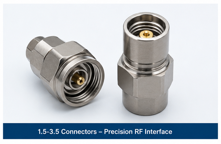
A 1.5-3.5 connector is a precision coaxial RF connector developed for high-frequency signal transmission. The designation refers to the approximate dimensions of the connector interface: the inner contact is approximately 1.5 mm in diameter, while the outer conductor has an approximate 3.5 mm diameter.
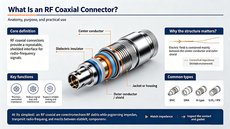
Like other coaxial RF connectors, a 1.5-3.5 connector consists of a center conductor, dielectric support, and outer conductor. Its geometry is carefully controlled to maintain a nominal 50-ohm characteristic impedance throughout the RF signal path.
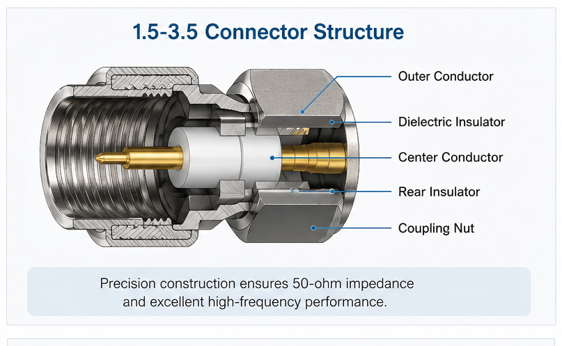
A 1.5-3.5 connector transfers an RF signal between two coaxial components while maintaining the electrical characteristics of the transmission line. The center contact carries the RF signal, while the outer conductor provides the return path and electromagnetic shielding.
Maintaining a consistent impedance is critical. Any sudden change in conductor diameter, dielectric geometry, or connector interface can create an impedance discontinuity. This discontinuity causes part of the RF energy to be reflected toward the source.
Precision machining and controlled connector geometry allow 1.5-3.5 connectors to minimize these discontinuities. This makes them particularly suitable for vector network analyzers, RF test equipment, microwave modules, and other precision systems.
Most 1.5-3.5 RF connectors use a 50-ohm interface, making them compatible with standard microwave transmission systems and RF test equipment.
Their precision interface is designed for high-frequency operation, helping reduce reflection and signal degradation in microwave applications.
The relatively small form factor makes 1.5-3.5 connectors suitable for compact RF modules, test fixtures, instrumentation, and high-density assemblies.
The threaded coupling mechanism provides a secure connection and helps maintain stable electrical contact during operation.
Exact specifications vary between manufacturers and product designs. When selecting a 1.5-3.5 connector, engineers should review the complete datasheet rather than relying only on the connector name.
| Parameter | Typical Consideration |
|---|---|
| Connector Type | Precision coaxial RF connector |
| Characteristic Impedance | 50 ohms |
| Frequency Range | Commonly used in microwave and millimeter-wave systems; exact range depends on design |
| Coupling | Threaded coupling |
| Interface | Approximately 1.5 mm inner / 3.5 mm outer dimensions |
| Applications | RF testing, telecommunications, radar, aerospace, instrumentation, and microwave equipment |
| Termination Options | PCB, cable, panel, bulkhead, and other configurations depending on the product |
One of the main advantages of 1.5-3.5 connectors is their ability to maintain good RF performance at high frequencies. Precision mechanical dimensions help control impedance and reduce unwanted reflections.
Connector loss becomes increasingly important as frequency increases. A well-designed 1.5-3.5 interface can provide low insertion loss, helping preserve signal power throughout the RF chain.
A carefully manufactured connector minimizes impedance discontinuities and can achieve low VSWR and good return loss. This is especially important for precision measurement systems where small RF errors can affect test results.
Compared with larger coaxial connector families, the compact dimensions of 1.5-3.5 connectors make them attractive for equipment where PCB space and mechanical packaging are limited.
Their electrical performance makes 1.5-3.5 connectors useful in RF laboratories, network analyzers, signal generators, spectrum analyzers, test fixtures, and calibration systems.
1.5-3.5 and SMA connectors are both threaded 50-ohm RF connectors, but they are designed with different electrical and mechanical performance targets.
| Feature | 1.5-3.5 Connector | SMA Connector |
|---|---|---|
| Primary Purpose | High-frequency precision RF applications | General microwave and RF applications |
| Size | Compact | Compact |
| Impedance | Typically 50 ohms | Typically 50 ohms |
| Frequency Capability | Designed for high-frequency operation; depends on design | Commonly used through microwave frequencies; exact limit depends on construction |
| Typical Applications | Precision instrumentation and high-frequency RF systems | RF modules, antennas, wireless equipment, test equipment |
Although these connectors may appear similar, they should not automatically be treated as interchangeable. Mechanical compatibility, interface dimensions, electrical specifications, and manufacturer-approved mating combinations should always be verified.
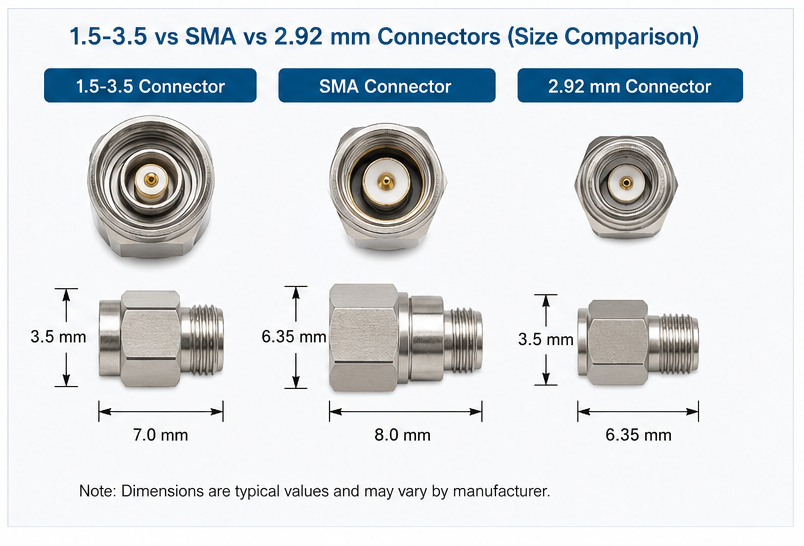
The 1.5-3.5 connector may also be compared with other high-frequency connector families such as 2.92 mm connectors. Both are used in demanding microwave applications, but their physical interfaces and intended performance ranges differ.
When selecting between them, engineers should evaluate the maximum operating frequency, insertion loss, return loss, VSWR, power handling, connector size, mating compatibility, and test-system requirements.
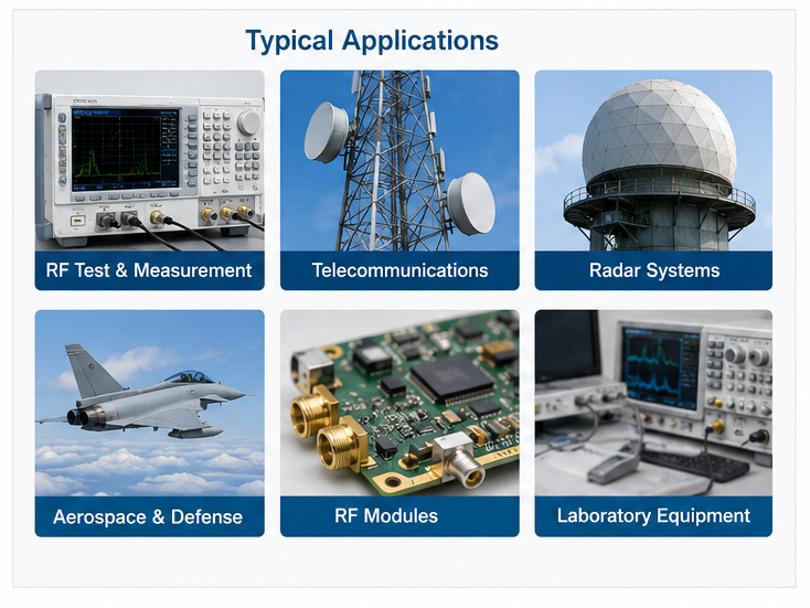
1.5-3.5 connectors are used in a wide range of high-frequency systems where reliable RF transmission is required.
Used in network analyzers, signal generators, spectrum analyzers, calibration equipment, RF test fixtures, and automated measurement systems.
Suitable for high-frequency communication equipment, RF front ends, wireless infrastructure, and signal distribution systems.
Precision RF connectors can be used in radar modules and microwave signal paths where stable transmission characteristics are important.
Compact high-frequency connectors can be integrated into RF modules, electronic warfare equipment, satellite systems, and other specialized platforms.
Their compact dimensions make them useful for connecting amplifiers, filters, attenuators, switches, couplers, and other microwave components.
Precision connector interfaces are valuable when repeatable measurements and low measurement uncertainty are required.
Improperly tightened connectors can create unstable electrical contact and change the measured RF performance. Precision RF systems should use the manufacturer's recommended torque procedure and appropriate tools.
Dust, oil, moisture, or other contaminants on the mating surfaces can increase contact resistance and cause impedance discontinuities. Connector interfaces should be kept clean and protected when not in use.
Excessive mechanical force or incorrect mating can damage the center contact. Damaged contacts may cause increased VSWR, intermittent connections, and poor repeatability.
RF connectors that look physically similar may have different interfaces. Using an incompatible adapter or forcing two connectors together can permanently damage precision mating surfaces.
At microwave and millimeter-wave frequencies, even relatively small mechanical imperfections can affect signal integrity. Connector dimensions, surface finish, dielectric geometry, center-contact alignment, and manufacturing tolerances all influence RF performance.
This is why precision manufacturing is particularly important for 1.5-3.5 connectors. A high-quality connector should provide consistent impedance, reliable mechanical coupling, repeatable RF characteristics, and stable performance over its intended operating conditions.
Yes. 1.5-3.5 connectors are generally designed as 50-ohm RF interfaces for microwave and high-frequency applications. Always verify the exact impedance specification of the product before use.
They are commonly used in RF test and measurement equipment, telecommunications, radar, aerospace, defense, microwave modules, and other high-frequency systems.
No. Although both are threaded RF connectors and may be used in similar systems, their interface dimensions and high-frequency performance characteristics are different. Compatibility must be confirmed from the manufacturer's specifications.
Start by checking operating frequency, impedance, VSWR, return loss, insertion loss, power handling, mechanical interface, mounting style, environmental requirements, and cable or equipment compatibility.
As frequency increases, small discontinuities become more significant relative to the signal wavelength. Precision connector geometry helps reduce reflections and maintain signal integrity.
1.5-3.5 connectors are compact, precision RF connectors designed for demanding microwave and high-frequency applications. Their 50-ohm architecture, controlled impedance, compact construction, and reliable threaded interface make them valuable for RF testing, telecommunications, radar, aerospace, and advanced microwave equipment.
When choosing a 1.5-3.5 connector, frequency capability should not be the only consideration. Engineers should also evaluate VSWR, return loss, insertion loss, power handling, mechanical compatibility, environmental performance, and connector durability. Selecting the correct connector and maintaining it properly can significantly improve the reliability and repeatability of a high-frequency RF system.
High-tech Enterprise, Feifeng Talent
Chief Engineer Wang graduated with a master's degree in high-power microwave from the Institute of Electronics, University of Chinese Academy of Sciences.
View Full Profile