




























What are QMA Connectors?
Quick Answer
A QMA connector is a 50 Ω snap-on coaxial connector with the same form factor as SMA but with a quick-lock coupling mechanism instead of a threaded nut. QMA connectors operate from DC to about 6 GHz (some to 18 GHz), handle 100 – 200 mating cycles, and are widely used in cellular base stations, antenna systems, and indoor RF distribution where fast, repeated connections are needed.
What Are QMA Connectors?
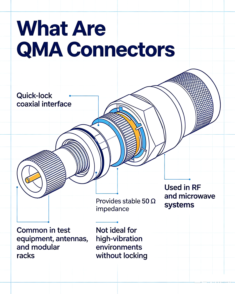
QMA stands for "Quick-lock MiniAture" — a standard developed by Quick Connect / Huber+Suhner. QMA is mechanically similar to SMA, but uses a spring-loaded snap coupling instead of a 6-sided threaded nut. The result:
- Mating time reduced by 80 % vs. SMA.
- Consistent torque and electrical performance on every connection.
- No tools required for installation.
- Excellent performance in vibration-prone applications.
QMA connectors are not compatible with SMA connectors — the coupling mechanisms are different. However, adapters between QMA and SMA are widely available.
Key Specifications
| Specification | Typical Value |
|---|---|
| Impedance | 50 Ω |
| Frequency Range | DC – 6 GHz (standard), up to 18 GHz |
| VSWR | ≤ 1.05:1 to 3 GHz, ≤ 1.15:1 to 6 GHz |
| Insertion Loss | < 0.1 dB at 3 GHz |
| Dielectric Withstanding Voltage | 1,000 V RMS |
| Insulation Resistance | ≥ 5 GΩ |
| Center Contact Resistance | ≤ 3 mΩ |
| Outer Contact Resistance | ≤ 2.5 mΩ |
| Mating Cycles | 100 – 200 (typical) |
| Coupling Retention | ≥ 100 N (axial force) |
| Temperature Range | −40 °C to +85 °C (typical) |
| Power Handling | ~150 W CW @ 2 GHz |
How QMA Works
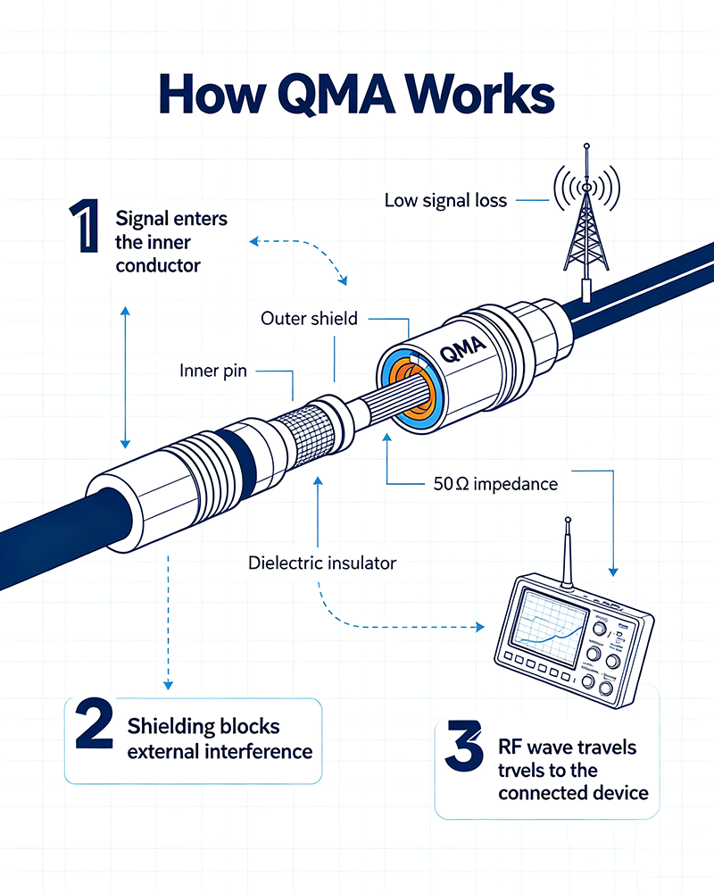
The QMA coupling mechanism consists of three spring-loaded locking tabs inside the female connector. When the male connector is pushed in and slightly rotated (about 30°), the tabs snap into a groove on the male's outer conductor. The connection is locked with a positive click and remains mechanically secure until the user pulls back the outer sleeve to release.
- Push & turn to mate (about 30° rotation).
- Pull outer sleeve to unlock and unmate.
- Visual / tactile confirmation of proper engagement.
Mechanical Features
Snap-Lock Coupling
Spring-loaded tabs lock into a groove with a positive click. Eliminates cross-threading and torque variation.
No Tools Required
Mating and un-mating are done by hand. Reduces installation time and torque-wrench dependency.
Consistent Electrical Performance
Repeatable mating force ensures VSWR and insertion loss are stable across every connection.
Vibration Resistant
Locked coupling holds firm under shock and vibration, ideal for mobile and aerospace use.
Dense Packing
Smaller footprint than SMA with N-type performance. Ideal for high-density panels.
100 – 200 Mating Cycles
Suitable for test fixtures and reconfigurable systems where SMA's threading would wear out.
QMA vs. SMA vs. N-Type
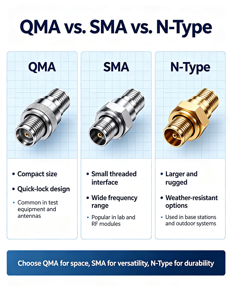
| Feature | QMA | SMA | N-Type |
|---|---|---|---|
| Coupling | Snap-lock | Threaded | Threaded |
| Frequency | DC – 6 GHz (18 GHz extended) | DC – 18 GHz | DC – 11 GHz (18 GHz precision) |
| Power | ~150 W | ~200 W | ~500 W |
| Mating Time | Fast (snap) | Slow (6 turns) | Slow (multiple turns) |
| Mating Cycles | 100 – 200 | 500 | 500 |
| Vibration | Excellent | Good (with proper torque) | Good (with proper torque) |
| Cost | Higher | Lower | Higher |
Electrical Performance
Low Frequency (≤ 3 GHz)
- VSWR ≤ 1.05:1
- Insertion loss < 0.05 dB
- Equivalent to SMA
Mid Frequency (3 ––6 GHz)
- VSWR ≤ 1.15:1
- Insertion loss < 0.1 dB
- Performance slightly below SMA
High Frequency (6 – 18 GHz)
- Extended-range QMA only
- Higher VSWR (1.30:1 typical)
- Less common than SMA
Real-World Applications
1. Cellular Base Station Equipment
QMA is the standard RF interconnect inside many cellular base stations where dense, repeatable connections speed assembly and field service.
2. Indoor Distributed Antenna Systems (DAS)
QMA is widely used in DAS equipment — ceiling antennas, splitters, and couplers — where fast, tool-free installation is critical.
3. Small Cells and Pico Cells
Compact RF modules benefit from QMA's small footprint and quick install.
3. RF Test & Measurement
Test fixtures and racks benefit from QMA's fast mating, though care is needed for high-cycle production testing.
4. Aerospace & Defense
Vibration-resistant coupling makes QMA attractive for airborne and shipboard RF systems.
5. Broadcast
Studio-transmitter links and inside broadcast racks use QMA for compact, quick service.
6. Industrial RF
Plasma generators, RF drying, and induction systems use QMA where frequent service is needed.
Installation Best Practices
- Align the male connector with the female socket and push straight in.
- Rotate about 30° clockwise until you feel a positive click.
- Do not over-rotate — only one direction is correct.
- To unmate, pull the outer sleeve of the female connector back while gently rotating counter-clockwise.
- Avoid side-load forces during mating — they can damage the center pin.
- Use proper torque on bulkhead-mount versions.
Common Mistakes
- Forcing the connector: misalignment bends the center pin.
- Mating QMA to SMA: mechanically incompatible, can damage both connectors.
- Exceeding rated frequency: performance degrades above 6 GHz.
- Side loading during mating: damages the locking tabs.
- Skipping visual inspection: dirt on the center contact causes poor VSWR.
How to Choose Between QMA and SMA
- Choose QMA when: installation speed matters, dense panel layouts, frequent reconfigurations, or vibration is expected.
- Choose SMA when: maximum frequency is needed (up to 18 GHz), low cost is critical, or mating cycles exceed 200.
- Choose N-type when: power handling above 200 W or low-loss up to 11 GHz is required.
Key Takeaways
- QMA is a snap-lock alternative to threaded SMA, optimized for fast installation.
- QMA is not mechanically compatible with SMA — use an adapter to bridge.
- Best suited for DC – 6 GHz applications.
- 100 – 200 mating cycles make QMA ideal for reconfigurable systems.
- Standard in cellular base stations, DAS, and small cells.
Frequently Asked Questions
What does QMA stand for?
QMA stands for Quick-Lock Miniature, indicating its push-and-twist locking mechanism and SMA-like form factor.
Is QMA compatible with SMA?
No. QMA and SMA have different coupling mechanisms and are not mechanically intermateable. Use a QMA-to-SMA adapter when needed.
What is the maximum frequency of QMA?
Standard QMA operates from DC to 6 GHz. Extended-range QMA is available up to 18 GHz with slightly higher VSWR.
How many mating cycles does QMA support?
QMA typically supports 100 – 200 mating cycles. This is less than SMA (500), but more than enough for most production and field-service applications.
Where is QMA commonly used?
QMA is standard in cellular base stations, distributed antenna systems (DAS), small cells, broadcast, and any application needing fast, repeatable RF connections in DC – 6 GHz range.
About the Author — MeiXun Team
Chief Engineer Wang
High-tech Enterprise, Feifeng Talent
Chief Engineer Wang graduated with a master's degree in high-power microwave from the Institute of Electronics, University of Chinese Academy of Sciences.
View Full Profile- RF Switch Circuit Diagram
- RF Switch
- Ohm's Law
- dBm to Watt
- mW to dBm
- Wavelength to Frequency
- RF Connector
- SMA Connector
- RF Switch Module
- RF Coupler
- RF PIN Switch
- Microwave Coaxial Switch
- PIN Switch
- Coaxial RF Switch
- Waveguide Switch
- Microwave Switch
- Low Noise Amplifier
- PIN Diode Switch
- Coaxial Switch
- RF Microwave Switch
- SPST Switch