
























The complete guide to Low Noise Amplifiers (LNAs): technical principles, applications, selection criteria, and leading manufacturers for 5G, radar, satellite, and SDR systems.
Sep 18 ,26


5G communication testing, wireless terminal automated testing
Aerospace communication systems
Precision measurement equipment, radio frequency signal control of radar transmitters
Communication and navigation systems
Optical communication module-related testing
Interconnection of wireless communication base stations
A differential amplifier is the fundamental building block of nearly every analog circuit. It amplifies the difference between two input signals while rejecting signals common to both — the property that makes it indispensable for noisy industrial, audio, RF, and instrumentation systems. This guide explains how it works, the common topologies, key specifications, where it shows up in real designs, and how to choose the right one for your application.
Quick answer: A differential amplifier has two inputs (Vin+, Vin−) and produces an output proportional to their difference: Vout = A × (Vin+ − Vin−). Common-mode signals (noise on both inputs) are rejected by the CMRR — often 80 to 120 dB in modern designs.
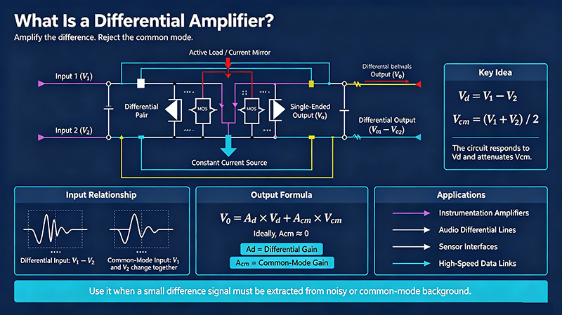
A differential amplifier is an electronic circuit that amplifies the voltage difference between two inputs while suppressing any voltage common to both. It is the foundation of operational amplifiers, instrumentation amplifiers, audio balanced lines, RF mixers, ADC drivers, and thousands of other analog building blocks.
The single most important property is the common-mode rejection ratio (CMRR) — the ability to ignore signals that appear on both inputs simultaneously (such as power-line hum, ground noise, or EMI pickup).
The classic op-amp-based differential amplifier uses four resistors to convert two single-ended inputs into one differential output:
When the resistor ratios are matched (R1/R2 = R3/R4), the output is:
| Parameter | Formula | Description |
|---|---|---|
| Differential gain (Ad) | R2 / R1 (matched) | Gain applied to the difference signal |
| Common-mode gain (Acm) | (R4·R1 − R3·R2) / (R1·(R3+R4)) | Ideally zero; depends on resistor matching |
| CMRR (dB) | 20 · log10(Ad / Acm) | Higher is better; 80+ dB typical, 120+ dB in instrumentation amps |
| PSRR | ΔVout / ΔVsupply | Rejection of supply noise |
| Input impedance (differential) | 2 × R1 | Set by input resistors |
| Topology | CMRR | Input Impedance | Best For |
|---|---|---|---|
| Op-amp difference amp (4-resistor) | 40–80 dB | 10–100 kΩ | Simple, low-cost |
| Instrumentation amp (3-op-amp) | 100–140 dB | 1–10 GΩ | Bridge sensors, ECG, strain gauges |
| Fully-differential op-amp | 80–120 dB | Differential | ADC drivers, differential signal chains |
| Current-feedback differential | 60–90 dB | Low | Wideband video, RF |
| Transformer-coupled | Passive | High | Audio, balanced lines, RF |
| BJT / MOS differential pair | 50–80 dB | Medium | Discrete design, very high frequency |
| Spec | Why It Matters | Typical Range |
|---|---|---|
| CMRR (DC) | Common-mode rejection at low frequency | 60–140 dB |
| CMRR (AC) | CMRR at signal frequency | Falls with frequency |
| PSRR | Power supply rejection | 60–120 dB |
| Input offset voltage | Output error at zero input | µV to mV |
| Input bias current | DC loading on source | pA to µA |
| Input impedance | Source loading | kΩ to GΩ |
| Gain bandwidth (GBW) | Frequency limit at gain of 1 | 1 MHz to 5 GHz |
| Slew rate | Large-signal speed limit | 1 V/μs to 5000 V/μs |
| Noise (input-referred) | Smallest signal detectable | nV/√Hz |
The 3-op-amp instrumentation amplifier is the gold standard when you need very high CMRR, very high input impedance, and adjustable gain from a single resistor. It uses two input buffers plus a difference amp:
Zero-drift op-amps achieve <1 µV offset and 130+ dB CMRR at DC.
Continuous on-chip calibration removes 1/f noise and drift.
Complete INAs in tiny packages simplify design.
Multi-GHz FDA drive 12/14-bit ADCs at IF frequencies.
Differential amps co-packaged with MEMS sensors for IoT.
Auto-tuning tools optimize CMRR, gain, and bandwidth trade-offs.
A differential amp uses a single op-amp with four resistors. An instrumentation amp uses three op-amps (two buffers + difference stage) and offers much higher CMRR, much higher input impedance, and gain adjustment from a single resistor.
CMRR (Common-Mode Rejection Ratio) measures how well the amp rejects signals common to both inputs. A CMRR of 100 dB means the amp rejects common-mode noise 100,000 times better than it amplifies differential signals.
Differential amplifiers reject common-mode noise such as ground loops, power-line hum, and EMI — signals that are the same on both inputs. Single-ended op-amps cannot do this.
Yes. Tie Vin− to ground (or a reference voltage) and drive Vin+ with the signal. The output is then A × Vin+, but CMRR suffers compared to a fully-differential input.
CMRR falls with frequency because the op-amp's open-loop gain decreases with frequency (gain-bandwidth product). Above a few hundred kHz, even a great op-amp has poor CMRR. Add a common-mode choke or use a fully-differential architecture for very high frequencies.
Use better-matched resistors (0.1% or better), reduce parasitic capacitance imbalance, add a common-mode choke, and ensure the source impedances on both inputs are equal.
• A differential amplifier amplifies the difference between two inputs while rejecting common-mode signals.
• Vout = A × (Vin+ − Vin−); CMRR quantifies common-mode rejection (higher is better).
• Choose a 4-resistor op-amp circuit for simplicity, an instrumentation amp for high CMRR, or a fully-differential op-amp for ADC drivers.
• Resistor matching and balanced PCB layout are the keys to high CMRR in practice.
• Differential amps dominate in instrumentation, audio, RF, ADC drivers, and any noisy environment where common-mode noise must be rejected.



High-tech Enterprise, Feifeng Talent
Chief Engineer Wang graduated with a master's degree in high-power microwave from the Institute of Electronics, University of Chinese Academy of Sciences.
View Full Profile