
























Learn what a differential amplifier is, how it works, common topologies (op-amp, instrumentation, fully-differential), key specifications like CMRR, applications, and design tips.
Sep 23 ,26


5G communication testing, wireless terminal automated testing
Aerospace communication systems
Precision measurement equipment, radio frequency signal control of radar transmitters
Communication and navigation systems
Optical communication module-related testing
Interconnection of wireless communication base stations
An integrator amplifier is an op-amp based active circuit whose output voltage is proportional to the time integral of the input signal. Built around an op-amp with a feedback capacitor and an input resistor, it produces an analog integration operation used in waveform generation, analog computing, signal conditioning, and control systems.
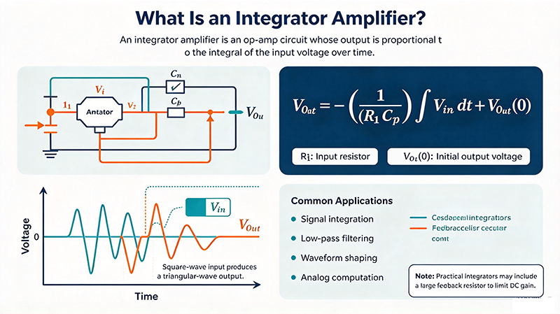
An integrator amplifier (often called an op-amp integrator) is a circuit that performs the mathematical operation of integration on an input voltage signal. It is the time-domain counterpart of the differentiator amplifier and is one of the most fundamental building blocks in analog signal processing.
Unlike a passive RC integrator, an active op-amp integrator offers:
The classic op-amp integrator uses one operational amplifier, one input resistor R, and one feedback capacitor C. The input signal is applied to the inverting input through R; the non-inverting input is grounded. The capacitor connects the output back to the inverting input.
Because the inverting input is held at a virtual ground, the current flowing through R equals Vin / R, and the same current charges the feedback capacitor C. The output voltage is therefore the negative integral of the input:
In the frequency domain this corresponds to an inverting gain that decreases at 20 dB/decade:
The corner frequency of the integrator is fa = 1 / (2πRC). Frequencies well above this value are integrated faithfully; below it the op-amp's open-loop gain limits accuracy.
Follow these practical steps when designing an integrator amplifier for a real application:
RC based on the lowest input frequency you need to integrate.
An ideal integrator has infinite DC gain, so even tiny input offset voltages and bias currents cause the output to drift toward one of the supply rails. Real designs must include a feedback resistor Rf in parallel with C to limit the low-frequency gain and prevent drift.
Adding a large feedback resistor Rf in parallel with the feedback capacitor produces the so-called lossy integrator. Its transfer function becomes:
Below 1 / (2πRfC) the circuit behaves as an inverting amplifier with gain −Rf/R; well above that corner it integrates the input.


High-tech Enterprise, Feifeng Talent
Chief Engineer Wang graduated with a master's degree in high-power microwave from the Institute of Electronics, University of Chinese Academy of Sciences.
View Full Profile