A diode is a two-terminal semiconductor electronic component that conducts current primarily in one direction. It has low resistance in one direction (forward bias) and high resistance in the opposite direction (reverse bias), making it essential for rectification, signal demodulation, voltage regulation, and circuit protection.
1. Definition of a Diode
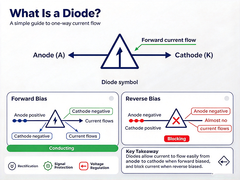
In electronics, a diode is defined as a passive semiconductor device with two terminals: an anode (A) and a cathode (K). The anode is the positive terminal, while the cathode is the negative terminal. A diode allows electric current to flow easily in one direction (from anode to cathode), but severely restricts current in the reverse direction.
The most common diode symbol is a triangle pointing toward a line. The flat side of the triangle is the anode; the line represents the cathode and acts as the barrier to reverse current flow.
Fig. 1 — Standard schematic symbol of a PN-junction diode
2. How Does a Diode Work?
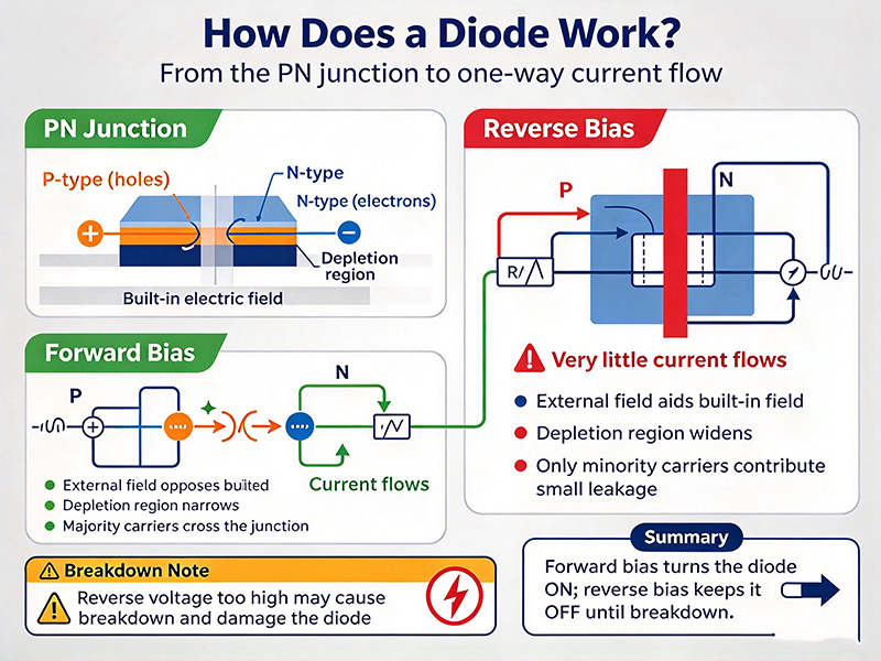
The working principle of a diode is based on the PN junction, the interface between P-type and N-type semiconductor materials inside the device.
2.1 Forward Bias
When the positive terminal of a voltage source is connected to the anode and the negative terminal to the cathode, the diode is forward-biased. Once the applied voltage exceeds the threshold voltage (about 0.7 V for silicon diodes, 0.3 V for germanium), the depletion region narrows and current flows easily through the device.
2.2 Reverse Bias
When the polarity is flipped, the diode is reverse-biased. The depletion region widens, and almost no current flows — only a tiny leakage current — as long as the reverse voltage stays below the breakdown voltage.
Key takeaway
A diode behaves like an electronic one-way valve: it passes current freely in forward bias and blocks it in reverse bias until the breakdown voltage is reached.
3. Main Types of Diodes
Different diode types are optimized for different applications. The most widely used include:
Rectifier Diode
Designed to convert AC to DC in power supplies; handles high currents.
Zener Diode
Operates in reverse breakdown to provide a stable reference voltage.
Light-Emitting Diode (LED)
Emits light when forward-biased; used in displays and indicators.
Schottky Diode
Low forward voltage drop and fast switching for high-frequency circuits.
Photodiode
Converts light into electrical current; used in light sensors.
TVS Diode
Transient voltage suppressor for ESD and surge protection.
4. Common Applications
Rectification — converting AC to DC in power adapters and chargers.
Signal demodulation — extracting audio from AM radio carriers.
Voltage regulation — using Zener diodes as reference sources.
Logic gates — building AND/OR circuits in digital electronics.
Reverse-polarity protection — guarding circuits from incorrect battery insertion.
Freewheeling / flyback — protecting transistors from inductive kickback in relays and motors.
5. Key Parameters to Know
Forward voltage (VF) — voltage drop across the diode when conducting.
Reverse breakdown voltage (VR) — maximum reverse voltage the diode tolerates.
Maximum forward current (IF) — highest continuous current the diode can handle.
Reverse leakage current (IR) — small current that flows under reverse bias.
Junction capacitance — important for high-frequency and switching applications.
6. How to Choose the Right Diode
When selecting a diode for your project, match the following criteria:
Forward current rating must exceed your circuit's maximum load current.
Reverse voltage rating must be at least 1.5× the maximum reverse voltage in your design.
Switching speed must be fast enough for high-frequency or pulse applications.
Package and thermal characteristics must fit your PCB layout and cooling strategy.
7. FAQ
Is a diode active or passive?
A diode is a passive component — it cannot amplify signals or provide power gain like a transistor.
Why is the threshold voltage of a silicon diode about 0.7 V?
It comes from the energy required to overcome the built-in potential of the silicon PN junction, typically around 0.6–0.7 V at room temperature.
Can a diode work with AC?
Yes. Rectifier diodes allow only the positive half of an AC waveform through, producing pulsating DC. Bridge rectifiers made of four diodes convert full AC waves into DC.
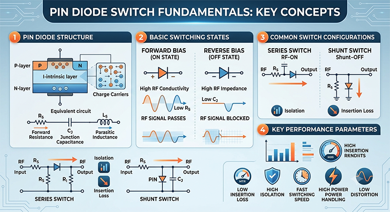
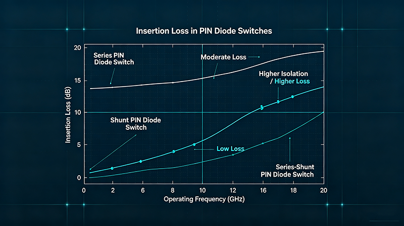
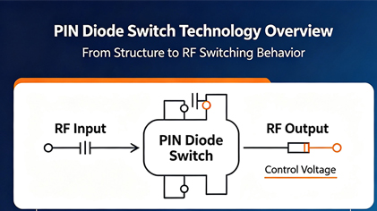
PIN diode switches are widely used in RF and microwave systems because of their high switching speed, excellent isolation, low insertion loss, and ability to handle high-frequency signals.
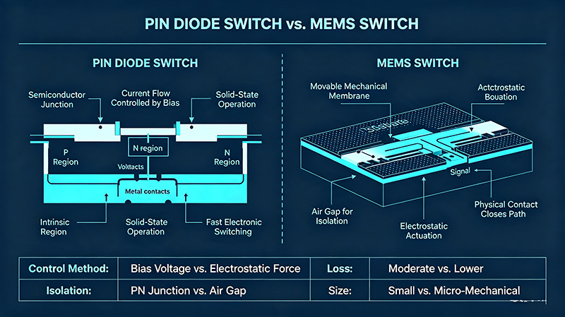
Expert comparison of PIN diode vs MEMS RF switches. Discover insertion loss, isolation, switching speed, power handling and which technology dominates 5G, mmWave and aerospace systems.
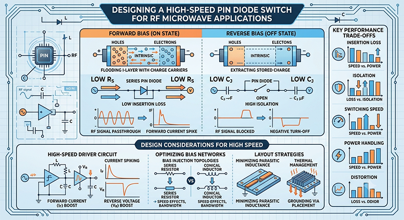
Designing a high-speed PIN diode switch requires a deep understanding of the delicate trade-offs between physical semiconductor characteristics, biasing topologies, and driver circuit dynamics.
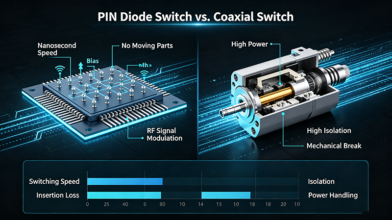
Detailed comparison of PIN diode switches vs coaxial switches. Learn the pros and cons of each technology and how to choose the right RF switch for your specific application requirements.
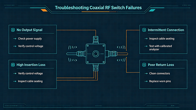
Learn how to troubleshoot RF microwave switch failures, including coaxial switch and PIN diode switch issues. Discover common causes, diagnostic methods, preventive maintenance, and expert solutions.
Discover the top 5 applications of PIN diode switches in radar and wireless communications. Learn how these solid-state switches enable advanced systems in defense, telecom, and sensing technologies.
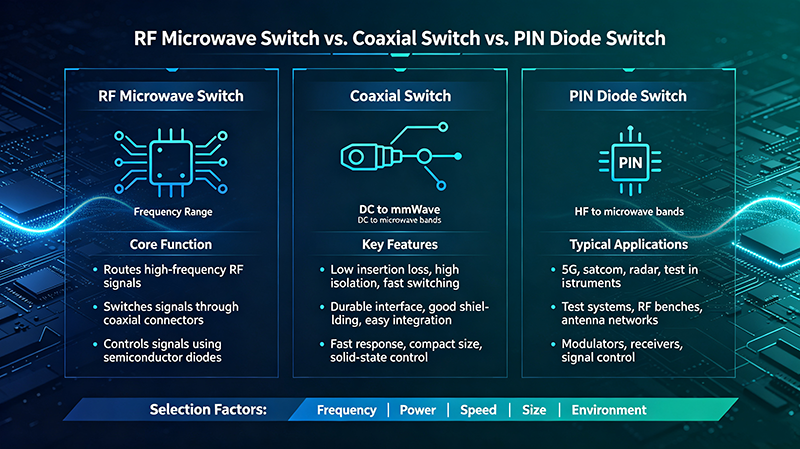
Understand the key differences between RF microwave switches, coaxial switches, and PIN diode switches. Learn about their working principles, applications, and how to choose the right switch for your RF system.
Jul 07 ,26
About the Author — MeiXun Team
Wang
Chief Engineer Wang
High-tech Enterprise, Feifeng Talent
Chief Engineer Wang graduated with a master's degree in high-power microwave from the Institute of Electronics, University of Chinese Academy of Sciences.
View Full Profile
Wang
Chief Engineer Wang
High-tech Enterprise, Feifeng Talent
Chief Engineer Wang graduated with a master's degree in high-power microwave from the Institute of Electronics, University of Chinese Academy of Sciences.
In the same year, he joined CETC 40/41 for work and study. He has been committed to the design and development of microwave switches for a long time.
He has applied for 27 patents as the first inventor in the microwave switch field, with 6 authorized invention patents and 14 utility model patents.
The products he developed cover various application platforms such as civilian testing, vehicle-mounted, shipborne, airborne, and missile-borne.