Why Decibels?
RF power spans an extraordinarily wide dynamic range. The weakest signals an RF engineer deals with are thermal noise at -174 dBm/Hz (about 4×10⁻²¹ watts per hertz of bandwidth), and the strongest are multi-kilowatt radar transmitters at +60 to +70 dBm. That is more than 60 dB of dynamic range, or 1,000,000,000,000× in linear units. Writing these numbers as watts or millivolts is impractical and error-prone — a small arithmetic slip can put you off by a factor of ten.
Decibels solve this problem. The decibel (dB) is a logarithmic unit that compresses huge ratios into manageable numbers. Calculations involving gain and loss become simple addition and subtraction. Cascaded stages (LNA + filter + cable + mixer) reduce to summing a column of dB numbers, which is far less error-prone than multiplying a column of voltage ratios.
dB — A Pure Ratio
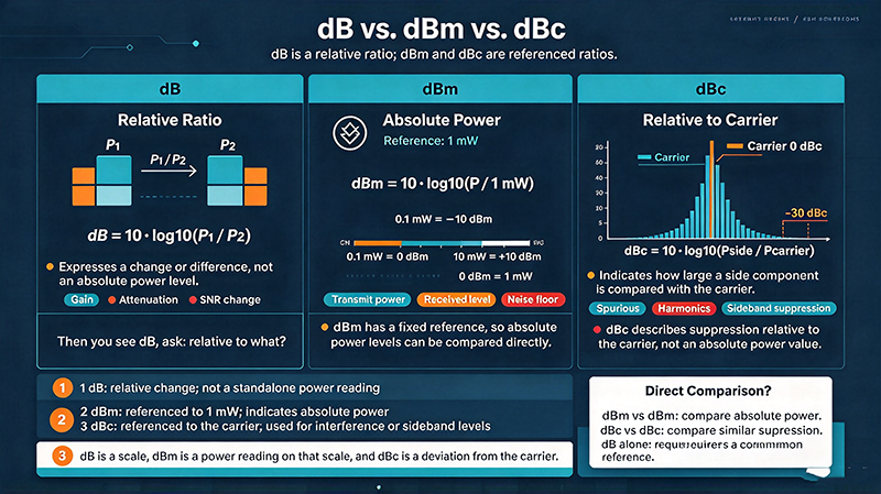
dB is dimensionless — it only makes sense as a ratio between two quantities. There are two formulas depending on whether you are comparing power or voltage:
For power: dB = 10·log10(P1 / P2)
For voltage (or current, with the same formula): dB = 20·log10(V1 / V2)
The factor is 10 for power (because power scales as voltage squared) and 20 for voltage. Using the wrong formula is one of the most common RF math mistakes.
Some useful dB values to memorize: +3 dB ≈ 2× power, +6 dB ≈ 4× power, +10 dB = 10×, +20 dB = 100×. Negative values: −3 dB ≈ ½ power, −10 dB = 1/10, −20 dB = 1/100. A cable that loses 3 dB delivers half its input power; a 20 dB attenuator leaves only 1% of the signal.
dBm — Absolute Power Referenced to 1 mW
dBm expresses an absolute power level referenced to 1 milliwatt. It is the universal power unit in RF datasheets, spectrum analyzer displays, and link budget calculations. The 'm' in dBm reminds you the reference is 1 milliwatt, not 1 watt.
0 dBm = 1 mW exactly. +30 dBm = 1 W exactly. +60 dBm = 1 kW. Conversely, −30 dBm = 1 µW, −60 dBm = 1 nW, −90 dBm = 1 pW. The relationship is:
P (mW) = 10^(dBm / 10)
RF engineers commit several key dBm values to memory: −174 dBm/Hz is thermal noise floor at room temperature, −100 dBm is roughly the receive level for a strong GPS signal, −70 dBm is a strong cellular signal, 0 dBm is the reference output of many bench signal generators, and +30 to +50 dBm is the output range of typical wireless transmitters.
dBc — Relative to the Carrier
dBc measures how many decibels a signal is below the carrier (or fundamental) frequency. The 'c' stands for 'carrier'. dBc is used to specify harmonics, spurious outputs, and phase noise in oscillators and transmitters.
If a transmitter's second harmonic is at -30 dBc, that harmonic is 30 dB weaker than the fundamental carrier. If its phase noise at 10 kHz offset is -90 dBc/Hz, the noise in 1 Hz of bandwidth at that offset is 90 dB below the carrier. dBc is always relative — to convert to an absolute level, add the carrier power in dBm: P_harmonic (dBm) = P_carrier (dBm) + dBc.
Quick Conversion Table
|
dBm
|
Watts
|
Typical Application
|
|
+60
|
1 kW
|
HF broadcast transmitter
|
|
+50
|
100 W
|
High-power radar
|
|
+40
|
10 W
|
VHF/UHF base station PA
|
|
+33
|
2 W
|
Wi-Fi AP output (802.11)
|
|
+27
|
0.5 W
|
Cellular PA (LTE)
|
|
+20
|
100 mW
|
BLE / Wi-Fi client
|
|
+10
|
10 mW
|
Sub-GHz radio
|
|
0
|
1 mW
|
Reference
|
|
-10
|
100 µW
|
Cellular receive
|
|
-30
|
1 µW
|
Strong Wi-Fi received
|
|
-40
|
0.1 µW
|
GPS
|
|
-60
|
1 nW
|
Bluetooth sensitivity
|
|
-100
|
10 fW
|
Deep-space signals
|
|
-174
|
~4 aW/Hz
|
Thermal noise floor (kTB)
|
Common Mistakes
Mixing dBm with dB is the most frequent RF arithmetic error. Adding 10 dB of gain to a −30 dBm signal gives −20 dBm — not −20 dB. Always carry the unit through the math: gain is in dB, absolute power is in dBm, harmonic content is in dBc.
Another common error is using the wrong formula when switching between power and voltage. A 6 dB voltage ratio is 2× voltage but only 4× power (because power scales as V²). A 3 dB voltage ratio is √2 ≈ 1.414 voltage but only 1.414² ≈ 2× power. Remember: +3 dB in voltage is +6 dB in power.
Practical Tips for Working with Decibels
When doing a link budget, list every component with its gain or loss in dB and its input/output power in dBm. Sum the gains and subtract the losses to get the net path gain; add that to the input power to get the output power. A quick sanity number is that the thermal noise floor is −174 dBm/Hz, and your received signal must be at least 10 dB above that for any usable demodulation.
When quoting a measurement, always include the bandwidth and the reference. −100 dBm in a 1 Hz bandwidth is dramatically different from −100 dBm in a 1 MHz bandwidth — the latter is 60 dB higher noise power. The same trap applies to phase noise: −90 dBc/Hz at 10 kHz offset is fundamentally different from −90 dBc at a 10 MHz offset.
Frequently Asked Questions
Q: What is dBi? A: dBi expresses antenna gain relative to an isotropic radiator. dBd expresses gain relative to a half-wave dipole. dBd + 2.15 = dBi.
Q: What is dBW? A: Same as dBm but referenced to 1 watt instead of 1 milliwatt. dBW = dBm − 30.
Q: What is dBµV? A: Voltage expressed in decibels relative to 1 microvolt. Common in EMC and receiver sensitivity specifications. 0 dBµV = 1 µV across 50 Ω corresponds to −107 dBm.
Q: Can I add dBm numbers? A: No. Adding 0 dBm + 0 dBm gives 3 dBm, not 0 dBm. Two 1 mW sources combined give 2 mW = 3 dBm. To add dBm, first convert to linear watts, sum, and convert back.
Engineering Notes from the Bench
Bench engineers develop an intuitive feel for dBm values that lets them estimate signal levels at a glance. The key reference points to internalize: 0 dBm is 1 mW, the output of most bench signal generators at default attenuation. -30 dBm is a strong cellular signal at the antenna. -100 dBm is roughly the sensitivity floor of a good receiver. Above +20 dBm you are starting to handle power levels that can damage unprotected test equipment. Above +30 dBm you absolutely need an external attenuator or a directional coupler with a known coupling factor.
Spectrum analyzer measurements should always be quoted with the resolution bandwidth (RBW) and video bandwidth (VBW) used. A noise floor of -100 dBm in 1 Hz RBW is dramatically different from -100 dBm in 1 MHz RBW — the latter is 60 dB higher in noise power. Phase noise numbers must include the offset frequency (10 kHz at -90 dBc/Hz means something specific to the synthesizer designer).
Case Study: Misunderstood dBc Reading
A satellite operator was troubleshooting a beacon signal that appeared 30 dB lower than expected on a spectrum analyzer. The on-call engineer read the analyzer display as -30 dBm and concluded the beacon transmitter had failed. After escalation, a senior engineer noticed the spectrum analyzer was set to read in dBm but the actual signal was being measured as a sideband relative to a much larger carrier. The correct reading was -30 dBc, which translated to -90 dBm absolute — a healthy signal, with the carrier 60 dB higher. The lesson: always confirm what your instrument's units mean in the context of the measurement.
Closing Thoughts
Decibels are the universal language of RF. Mastering the difference between dB (ratio), dBm (absolute power), dBc (relative to carrier), and dBi/dBd (antenna gain) is the foundation for every RF design, measurement, and troubleshooting task. Once you can do dB math fluently in your head, the rest of RF engineering becomes far more approachable.
Industry Applications and Use Cases
Across telecommunications, aerospace, defense, medical imaging, and automotive radar, the concepts covered in this guide show up in every RF design. From 5G base stations deploying massive MIMO antenna arrays with dozens of Wilkinson dividers per panel, to satellite payloads where every decibel of link budget determines the success of a multi-million-dollar mission, the principles remain the same: measure carefully, design with margin, and verify with the right instrument.
Medical applications add another wrinkle: MRI machines operate at the Larmor frequency of hydrogen (42.58 MHz/Tesla) and require extraordinarily low noise and high stability. Test systems for MRI receivers must minimize cable loss between the imaging coil and the low-noise preamplifier — often mounted directly on the coil housing — because every dB of loss degrades diagnostic image quality. The same matching, cabling, and LNA placement principles apply.
Automotive radar at 77 GHz is one of the fastest-growing RF domains. Each modern car may contain 5–10 mmWave radar units for adaptive cruise control, blind-spot detection, and automated emergency braking. These radar modules contain calibrated Wilkinson dividers, matched patch antennas, beam-steering phase shifters, and integrated FMCW synthesizers — all built on low-cost PCB substrates and tested in production at volumes exceeding 100 million per year. The principles taught in this guide are what make that volume manufacturing possible.
Advanced Design Considerations
Beyond the basics covered above, several advanced topics deserve attention as your designs mature. Multi-physics simulation — coupling electromagnetic, mechanical, and thermal effects in a single simulation — is increasingly important at mmWave frequencies where small dimensional changes from thermal expansion can shift the operating frequency. Tools like ANSYS HFSS, CST Studio Suite, and Cadence Clarity now include multi-physics capabilities that integrate structural and thermal solvers with the RF simulator.
Machine learning is beginning to appear in RF design. Surrogate models trained on simulation data can predict S-parameters 1000× faster than running the full EM simulation, enabling design space exploration that was previously impossible. Tools like Google Brain's RF antenna design work and Cadence's Cerebrus are early examples of where the field is heading. For now, these tools augment rather than replace the engineer's judgment — they accelerate iteration but the final design still needs to be understood, verified, and signed off by an experienced engineer.
Standards, Compliance, and Regulation
Every RF system must comply with applicable regulatory standards. In the United States, Part 15 of the FCC rules governs intentional radiators and unintentional emissions. The European Union's Radio Equipment Directive (RED) does similar work. Specific applications have additional standards: ETSI EN 301 893 for 5 GHz Wi-Fi, ETSI EN 302 500 for UWB, and many others. Military and aerospace applications have additional standards: MIL-STD-461 for EMI, MIL-STD-810 for environmental, and MIL-STD-1540 for product assurance.
Compliance testing is a discipline of its own. Compliance test labs use specialized instruments (spectrum analyzers with quasi-peak detectors, EMI receivers calibrated to CISPR standards) and follow specific procedures. The measurement uncertainty of compliance tests is typically ±3 to ±6 dB — much wider than production test measurements, but required for regulatory acceptance. Plan for compliance testing early in your design cycle; retrofitting a product to meet EMI requirements after the design is finalized is expensive and time-consuming.
Career and Skill Development in RF Engineering
RF engineering is a deep specialty with strong demand and excellent compensation. The barrier to entry is high: unlike software, you cannot iterate in seconds, and the cost of mistakes is paid in physical hardware. Yet for engineers who take the time to develop intuition, RF offers some of the most satisfying engineering work available — every component choice has a measurable effect, and every measurement reveals something about the physical world.
For those starting out, build a home lab. Even a modest setup with a cheap SDR (RTL-SDR, HackRF, or Airspy), a few antennas, and some cables will let you explore the RF spectrum in ways that no simulator can. Add a low-end spectrum analyzer (Rigexpert, TinySA) when you can afford it, and a used VNA from eBay when the budget allows. The hands-on experience with real signals, real cables, and real instruments is what builds intuition that no textbook can provide.
Stay current by reading industry publications (Microwave Journal, RF Globalnet, Microwaves & RF), attending conferences (IMS, EuMW, IEEE MTT-S), and joining professional communities (IEEE MTT-S, ACM SIGCOMM for networking RF). The field evolves rapidly — mmWave 5G, satellite internet, and automotive radar were niche markets 10 years ago and are now mainstream. The engineers who built those markets started by mastering exactly the fundamentals covered in this article.