What Is an RF Power Amplifier?
An RF power amplifier (RF PA) is an electronic device designed to increase the power level of a radio-frequency signal before it is transmitted to an antenna, load, or another RF system. RF power amplifiers are essential components in wireless communication, radar, satellite communication, broadcasting, electronic warfare, test equipment, and many other high-frequency applications.
Unlike a low noise amplifier, which is primarily designed to amplify weak signals while introducing minimal noise, an RF power amplifier focuses on delivering sufficient output power, efficiency, linearity, and reliability to the system.
What Is an RF Power Amplifier?
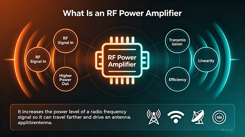
An RF power amplifier is an active RF component that increases the power of a radio-frequency signal to a level suitable for transmission or driving a high-power RF load. The amplifier receives a relatively low-power RF input signal and uses a DC power supply to produce a higher-power RF output signal.
RF Power Amplifier Definition
An RF power amplifier is a circuit or module that amplifies radio-frequency signals while providing the required output power, gain, efficiency, and linearity for a specific RF application.
RF power amplifiers typically operate at frequencies ranging from several megahertz to tens of gigahertz, depending on their design and application. The output power can range from milliwatts in compact wireless devices to hundreds or thousands of watts in specialized RF transmitters.
The primary purpose of an RF PA is not simply to increase voltage or current. Instead, it must efficiently deliver RF power to the intended load while maintaining acceptable signal quality and avoiding excessive heat generation.
How Does an RF Power Amplifier Work?
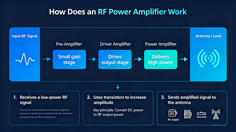
The basic operating principle of an RF power amplifier is relatively straightforward. A low-power RF signal is applied to the input of the amplifier. Active semiconductor devices use energy from a DC power supply to increase the signal's RF power. Matching networks then transform the impedance between the amplifier and the source or load to maximize power transfer.
A simplified RF power amplifier signal path can be represented as:
RF Input Signal → Driver Stage → Power Amplifier Stage → Matching Network → RF Output
The RF input signal controls the active device, while the DC supply provides the energy required to generate a larger RF output signal. The amplifier does not create RF energy from nothing; it converts part of the DC input power into RF output power.
1. RF Input
The input stage receives the RF signal from a transceiver, oscillator, mixer, driver amplifier, or other RF source. The input power is normally much lower than the desired output power.
2. Driver Stage
A driver stage may be used to increase the signal level before it reaches the final power transistor. This allows the final stage to operate at its required drive level and improves overall system performance.
3. Power Amplification Stage
The final amplifier stage uses one or more active semiconductor devices to provide the required RF output power. Common technologies include LDMOS, GaN, GaAs, and silicon RF transistors.
4. Impedance Matching
RF matching networks are used at the input and output of the amplifier. Proper impedance matching reduces reflections and improves power transfer between the amplifier, transmission line, and load.
5. RF Output
The amplified signal is delivered to an antenna, transmission line, RF load, or another subsystem. Depending on the application, additional filtering or switching may be required after the amplifier.
Main Components of an RF Power Amplifier
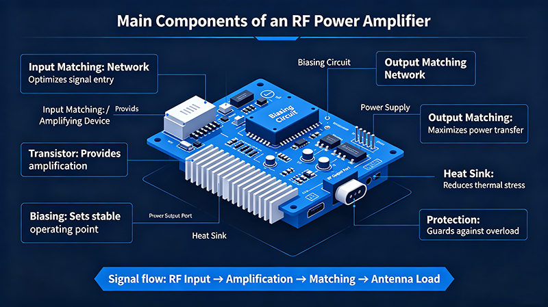
An RF power amplifier is normally more than a single transistor. A practical RF PA may include multiple electrical and mechanical components designed to provide stable and reliable operation.
RF Transistor
The active transistor provides the fundamental amplification function. GaN, GaAs, LDMOS, and silicon technologies are widely used in modern RF power amplifiers.
Matching Networks
Input and output matching networks optimize impedance transformation, power transfer, gain, and efficiency across the operating frequency range.
Bias Circuit
The bias network supplies the correct DC voltage and current to the active device and establishes the desired operating point.
Thermal Management
Heat sinks, thermal interfaces, cooling systems, and suitable PCB layouts may be required to dissipate heat generated during high-power operation.
Types of RF Power Amplifiers
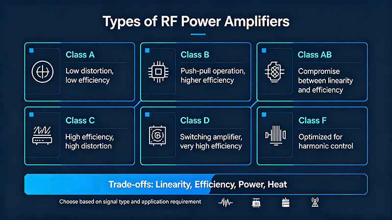
RF power amplifiers can be classified according to their circuit topology, transistor technology, operating frequency, output power, and application. One of the most common classifications is based on amplifier operating class.
A Class A amplifier conducts for the entire RF signal cycle. It provides excellent linearity and relatively low distortion, making it useful in applications where signal fidelity is more important than maximum efficiency.
The major disadvantage is low theoretical efficiency compared with switching-oriented amplifier classes. Significant DC power can be converted into heat, particularly when the amplifier operates at high power.
Class B RF Power Amplifier
A Class B amplifier ideally conducts for approximately half of the RF cycle. It can achieve higher efficiency than Class A, although crossover distortion may affect linearity.
Class AB RF Power Amplifier
Class AB operation provides a compromise between linearity and efficiency. The active device conducts for more than half but less than the full RF cycle. Because of this balance, Class AB amplifiers are widely used in RF transmitters and communication systems.
Class C RF Power Amplifier
Class C amplifiers conduct for less than half of the signal cycle. They can provide high efficiency but generally have poorer linearity. They are therefore more appropriate for applications involving constant-envelope signals or systems where high efficiency is prioritized.
Class D, E, and F RF Power Amplifiers
Class D, E, and F amplifiers use switching or harmonic-control techniques to achieve high efficiency. These amplifier architectures can be attractive for high-efficiency RF transmitters, although their suitability depends strongly on frequency, bandwidth, waveform, and system requirements.
Solid-State RF Power Amplifiers
Modern RF systems commonly use solid-state power amplifiers based on semiconductor technologies such as GaN, GaAs, LDMOS, and silicon. Solid-state RF PAs can provide compact dimensions, fast response, high reliability, and precise electrical control.
Key RF Power Amplifier Specifications
Choosing an RF power amplifier requires more than looking at its maximum output power. Engineers should evaluate several specifications to determine whether the amplifier is suitable for a particular system.
|
Specification
|
What It Means
|
Why It Matters
|
|
Frequency Range
|
The RF frequency range over which the amplifier is designed to operate.
|
Determines compatibility with the target RF system.
|
|
Gain
|
The increase in RF signal power between the input and output.
|
Determines how much drive power is required.
|
|
Output Power
|
The RF power delivered by the amplifier to the load.
|
Determines transmitter range and system capability.
|
|
Efficiency
|
The percentage of DC input power converted into useful RF output power.
|
Strongly affects power consumption and thermal performance.
|
|
Linearity
|
How accurately the amplifier reproduces the input waveform without distortion.
|
Critical for modulated communication signals.
|
|
Noise Figure
|
The additional noise introduced by the amplifier.
|
Generally more important in sensitive receive chains than transmit PAs.
|
|
Input and Output VSWR
|
Measures impedance mismatch at the amplifier ports.
|
Important for power transfer and device protection.
|
|
P1dB
|
The approximate point where amplifier gain compresses by 1 dB.
|
Indicates the usable linear output-power region.
|
|
IP3
|
A measure associated with third-order nonlinear distortion.
|
Important in systems with multiple closely spaced signals.
|
RF Power Amplifier Efficiency
Efficiency is one of the most important characteristics of an RF power amplifier, particularly in high-power transmitters and battery-powered wireless equipment.
A simplified power-added efficiency relationship can be expressed as:
PAE = (RF Output Power − RF Input Power) ÷ DC Input Power × 100%
Higher efficiency means that a greater proportion of the supplied DC energy is converted into useful RF power rather than heat.
Poor efficiency increases power consumption and thermal requirements. In high-power RF equipment, thermal management can become one of the most significant design challenges. Therefore, RF amplifier efficiency affects not only electrical performance but also system size, reliability, cooling requirements, and operating cost.
Why Is Linearity Important?
Linearity describes how accurately an RF power amplifier reproduces the input signal as its output power increases. A highly nonlinear amplifier can introduce harmonic distortion, intermodulation products, spectral regrowth, and unwanted interference.
Linearity is particularly important for communication systems using complex modulation schemes such as QAM, OFDM, and other high-data-rate waveforms.
When an RF PA is driven beyond its linear operating region, gain compression occurs. The output power no longer increases proportionally with input power. Operating too close to saturation can significantly degrade signal quality.
Important: Maximum RF output power is not always the same as usable linear output power. Engineers should evaluate P1dB, compression characteristics, EVM, ACLR, IMD, and other relevant linearity parameters when designing a communication transmitter.
Applications of RF Power Amplifiers
RF power amplifiers are used in almost every system that needs to transmit RF energy at a useful power level.
Wireless Communication
RF PAs are fundamental components in cellular base stations, mobile communication equipment, Wi-Fi systems, private wireless networks, and other radio transmitters. They amplify the RF signal before it reaches the antenna.
5G Communication
5G infrastructure requires RF power amplifiers capable of operating at a range of frequencies while maintaining high efficiency and linearity. Massive MIMO and beamforming systems may use multiple RF amplifier channels to control individual antenna elements.
Radar Systems
Radar transmitters use RF power amplifiers to generate high-power pulses or continuous-wave signals. Depending on the radar architecture, the amplifier may need high peak power, high efficiency, wide bandwidth, or excellent pulse performance.
Satellite Communication
RF power amplifiers are used in satellite payloads, ground stations, uplink systems, and other satellite communication equipment. High efficiency is particularly valuable in space applications because available electrical power and thermal dissipation are limited.
Electronic Warfare
Electronic warfare systems can require broadband and high-power RF amplification for signal generation, jamming, electronic countermeasures, and other RF operations.
RF Test Equipment
RF power amplifiers are also used in signal generators, automated test systems, component testing, antenna testing, EMC testing, and laboratory measurement equipment where a controlled high-power RF signal is required.
How to Choose an RF Power Amplifier
Selecting the correct RF power amplifier requires matching its electrical and mechanical characteristics with the requirements of the complete RF system.
1. Determine the Operating Frequency
First identify the required frequency range. An amplifier designed for sub-GHz applications may not be suitable for microwave or millimeter-wave frequencies. Check both the nominal frequency and required bandwidth.
2. Determine the Required Output Power
Define the required continuous-wave or pulsed output power. It is generally preferable to provide sufficient power margin rather than continuously operate an amplifier at its absolute maximum rating.
3. Check Gain
Determine the available input drive power and calculate how much gain is necessary. If the source signal is too weak, a driver amplifier may be required before the final power stage.
4. Evaluate Linearity
For communication applications, check the amplifier's linearity specifications. P1dB alone may not provide enough information for systems using complex modulation.
5. Compare Efficiency
Higher efficiency can reduce power consumption and simplify thermal management. This is particularly important for battery-powered equipment, compact RF modules, and high-power transmitters.
6. Consider Thermal Requirements
Estimate the heat generated during normal operation and verify that the available heat sink, enclosure, PCB, or cooling system can maintain the amplifier within its specified operating temperature range.
7. Check VSWR and Protection
RF amplifiers can be sensitive to impedance mismatch. Consider input and output VSWR specifications as well as protection features such as over-temperature, over-current, over-voltage, and reflected-power protection.
8. Consider Package and Integration Requirements
For system integration, evaluate RF connectors, package dimensions, mounting configuration, DC supply requirements, control interfaces, cooling provisions, and environmental specifications.
RF power amplifiers and low noise amplifiers are both RF active components, but they serve very different purposes.
|
Feature
|
RF Power Amplifier
|
Low Noise Amplifier
|
|
Primary Function
|
Increase RF output power
|
Amplify weak RF signals
|
|
Typical Location
|
Transmit chain
|
Receive chain
|
|
Main Design Priority
|
Output power, efficiency, and linearity
|
Low noise figure, gain, and sensitivity
|
|
Power Handling
|
Usually high
|
Usually low
|
|
Thermal Management
|
Often critical
|
Generally less demanding
|
In a typical RF communication system, the RF power amplifier is located near the end of the transmit chain, while the LNA is normally positioned near the beginning of the receive chain. The PA provides transmission power, whereas the LNA preserves and amplifies weak received signals with minimal additional noise.
RF Power Amplifier Technologies
GaN RF Power Amplifiers
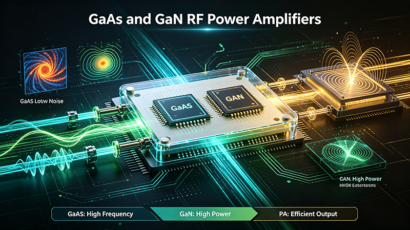
Gallium nitride, or GaN, is widely used for high-frequency and high-power RF applications. GaN devices can provide high power density, high breakdown voltage, and strong efficiency, making them attractive for radar, 5G, satellite communication, and electronic warfare systems.
GaAs RF Power Amplifiers
Gallium arsenide, or GaAs, offers strong high-frequency performance and is commonly used in microwave and millimeter-wave applications. GaAs technology can provide excellent gain and RF characteristics at high frequencies.
LDMOS RF Power Amplifiers
LDMOS technology has been widely adopted for RF power amplification, particularly in cellular infrastructure and broadcast systems. LDMOS devices offer mature manufacturing technology, good power handling, and strong reliability.
Common Challenges in RF Power Amplifier Design
Designing an RF power amplifier requires careful attention to electrical, thermal, and mechanical factors. Several challenges can significantly influence overall performance.
-
Thermal management: High output power can generate substantial heat.
-
Impedance matching: Poor matching can reduce efficiency and increase reflected power.
-
Nonlinearity: Excessive drive can produce compression and distortion.
-
Stability: The amplifier must remain stable across the intended frequency and load conditions.
-
Bandwidth: Wideband applications can make impedance matching and efficiency more difficult.
-
Power supply design: High-power RF amplifiers require clean and stable DC power.
-
EMI and isolation: Proper PCB layout, shielding, and grounding are necessary to prevent unwanted coupling and oscillation.
RF Power Amplifier Design Considerations
Successful RF PA design requires optimization across the complete signal chain. The transistor itself is only one part of the overall design. Input matching, output matching, bias networks, harmonic filtering, PCB layout, thermal management, and protection circuits all influence performance.
At microwave frequencies, PCB material and transmission-line geometry become increasingly important. Trace dimensions, dielectric properties, connector transitions, grounding structures, and component parasitics can significantly affect impedance and RF performance.
For high-power designs, the designer must also consider load-pull characteristics, device thermal resistance, safe operating area, harmonic termination, electromagnetic compatibility, and long-term reliability.
Frequently Asked Questions
What does an RF power amplifier do?
An RF power amplifier increases the power of a radio-frequency signal so that it can drive an antenna, transmission line, or RF load at the required power level.
Where is an RF power amplifier used?
RF power amplifiers are used in wireless communication, 5G base stations, radar, satellite communication, broadcasting, electronic warfare, RF test equipment, and many other RF transmission systems.
What is the difference between an RF amplifier and an RF power amplifier?
An RF amplifier is a broad term for an amplifier operating at radio frequencies. An RF power amplifier specifically focuses on delivering relatively high RF output power, usually at the final stage of a transmitter.
Why is RF power amplifier efficiency important?
Higher efficiency means more DC input power is converted into useful RF output power and less energy is dissipated as heat. This can reduce power consumption and thermal-management requirements.
What is P1dB in an RF power amplifier?
P1dB, or the 1 dB compression point, indicates the approximate output power at which the amplifier's gain has decreased by 1 dB from its small-signal value. It is an important indicator of the amplifier's linear operating range.
Is a GaN RF power amplifier better than a GaAs amplifier?
Neither technology is universally better. GaN is particularly attractive for high-power and high-power-density applications, while GaAs can provide excellent high-frequency performance. The best choice depends on frequency, output power, efficiency, bandwidth, linearity, cost, and application requirements.
Can an RF power amplifier be used as an LNA?
Generally, an RF power amplifier is not an appropriate substitute for a low noise amplifier. An LNA is optimized for low noise figure and weak-signal amplification, while an RF PA is optimized for output power, efficiency, and power handling.
Conclusion
An RF power amplifier is a critical component in RF transmission systems because it increases a radio-frequency signal to the power level required to drive an antenna or other RF load. Its performance depends on several factors, including output power, gain, efficiency, linearity, frequency range, VSWR, thermal performance, and reliability.
Modern RF power amplifiers use technologies such as GaN, GaAs, LDMOS, and silicon to meet the requirements of applications ranging from wireless communication and 5G to radar, satellite communication, electronic warfare, and RF test systems.
When selecting an RF power amplifier, engineers should evaluate the complete set of electrical, thermal, mechanical, and application requirements rather than focusing on output power alone. The right RF PA can improve transmitter efficiency, signal quality, reliability, and overall system performance.
Related topics: RF power amplifier, RF amplifier, RF PA, microwave power amplifier, high power RF amplifier, RF transmitter amplifier, GaN RF power amplifier, RF amplifier design, RF power amplifier efficiency, RF amplifier gain, RF power amplifier applications.