A DPDT switch, or Double Pole Double Throw switch, is one of the most versatile electromechanical switching components used in electronic and electrical circuits. Its ability to control two separate circuits simultaneously and route each circuit between two different paths makes it particularly useful for polarity reversal, motor control, signal routing, and mode selection.
Understanding the mechanics of a DPDT switch is essential for engineers, technicians, students, and electronics enthusiasts. Although the name may initially sound complicated, the operating principle becomes straightforward once the meanings of double pole and double throw are understood.
What Is a DPDT Switch?
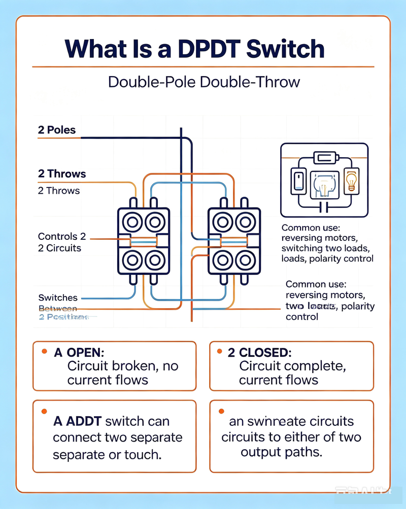
A DPDT switch is a switch with two independent poles and two possible switching positions or throws for each pole. In practical terms, it can control two separate electrical circuits at the same time and connect each circuit to one of two possible outputs.
DPDT = Double Pole Double Throw
-
Double Pole: The switch controls two separate electrical circuits.
-
Double Throw: Each circuit can be connected to one of two different terminals or paths.
A standard DPDT switch is often described as electrically equivalent to two SPDT (Single Pole Double Throw) switches mechanically linked together. When the switch actuator moves, both poles change position simultaneously.
Basic Structure of a DPDT Switch
Most conventional DPDT switches contain six primary terminals. These terminals are generally arranged in two rows of three terminals or another configuration that represents two independent SPDT switching sections.
Common Terminals
The common terminals are connected to the moving contacts inside the switch. These terminals are usually the input points for the circuits being controlled.
Throw Terminals
Each pole can connect its common terminal to one of two throw terminals, allowing the electrical path to change when the switch is actuated.
Moving Contacts
Internal conductive contacts physically move when the switch lever, toggle, slide, or actuator is operated.
Mechanical Actuator
The actuator transfers mechanical movement to the internal contacts, causing both poles to switch simultaneously.
How Does a DPDT Switch Work?
The mechanical operation of a DPDT switch is based on synchronized movement. Each pole has a common terminal and two possible connection terminals. When the actuator changes position, the internal contact for each pole moves from one throw terminal to the other.
For example, consider two poles identified as Pole A and Pole B:
Position 1:

Pole A: Common A → Throw A1
Pole B: Common B → Throw B1

Position 2:

Pole A: Common A → Throw A2
Pole B: Common B → Throw B2
The key mechanical characteristic is that both poles operate together. This synchronized movement allows the switch to perform coordinated changes in multiple circuits with a single mechanical action.
Understanding the Internal Mechanics
Inside a mechanical DPDT switch, electrical contacts are mounted within an insulated housing. The actuator mechanism moves conductive components between fixed contacts. Depending on the switch design, the movement may be produced by a toggle lever, rocker, slide mechanism, push button, rotary selector, or relay actuator.
1. Mechanical Movement
When force is applied to the actuator, mechanical energy is transferred through an internal linkage. The linkage moves the conductive contacts associated with both poles.
2. Contact Transfer
As the actuator changes position, the movable contact disconnects from one fixed terminal and connects to another. The exact switching sequence depends on whether the switch is designed as break-before-make or make-before-break.
3. Simultaneous Pole Switching
The two poles are mechanically coupled. This means both electrical circuits change their connections during the same switching operation. The circuits may be electrically isolated from each other while still sharing the same mechanical actuator.
4. Stable or Momentary Operation
Some DPDT switches remain in their selected position until manually changed again. These are known as maintained switches. Others automatically return to a default position after the actuator is released. These are called momentary switches.
DPDT Switch Terminal Configuration
|
Terminal Type
|
Function
|
Typical Use
|
|
Common Pole 1
|
Connects to one of two outputs
|
First circuit input
|
|
Throw 1A
|
First possible connection for Pole 1
|
Output or circuit path
|
|
Throw 1B
|
Second possible connection for Pole 1
|
Alternative output or path
|
|
Common Pole 2
|
Connects to one of two outputs
|
Second circuit input
|
|
Throw 2A
|
First possible connection for Pole 2
|
Output or circuit path
|
|
Throw 2B
|
Second possible connection for Pole 2
|
Alternative output or path
|
Important: The physical terminal layout varies between manufacturers and switch types. Always check the manufacturer's datasheet or test the terminals with a multimeter before connecting the switch to a circuit.
DPDT Switch Wiring Principle
The wiring method depends on the intended function. One of the most common applications is polarity reversal. Because a DPDT switch can simultaneously change two electrical connections, it can reverse the positive and negative connections applied to a load.
Polarity Reversal Wiring
In a polarity-reversing circuit, the power supply connections are cross-wired through the DPDT switch. When the switch changes position, the polarity delivered to the load is reversed.
This principle is widely used for:
-
Reversing DC motor direction
-
Changing actuator movement direction
-
Controlling linear actuators
-
Reversing electromagnetic devices
-
Changing battery polarity in specific circuit designs
DPDT Switch for DC Motor Direction Control
A particularly important application of the DPDT switch is DC motor reversal. A brushed DC motor changes its direction of rotation when the polarity of its supply voltage is reversed.
By wiring the power source and motor terminals in a crossed configuration, a DPDT switch can perform this polarity reversal with a single movement of the actuator.
Switch Position 1: Motor receives positive voltage on Terminal A and negative voltage on Terminal B, causing rotation in one direction.
Switch Position 2: Motor receives negative voltage on Terminal A and positive voltage on Terminal B, reversing the motor's direction.
This simple mechanical switching method is commonly used in small motor controllers, automotive accessories, robotics, industrial mechanisms, and actuator systems.
DPDT Switch Contact Types
The electrical behavior during switching is also important. DPDT switches can use different contact transition mechanisms.
Break-Before-Make
A break-before-make switch disconnects the existing circuit before connecting the new circuit. This creates a brief open state during switching.
This configuration is useful when the two outputs must never be connected together.
Make-Before-Break
A make-before-break switch establishes the new connection before fully disconnecting the previous one. This creates a brief overlap between the two connections.
This configuration may be useful in specialized circuits where uninterrupted electrical continuity is required. However, it must be selected carefully because temporary connection between two circuits may cause faults in inappropriate applications.
Common Applications of DPDT Switches
DPDT switches are widely used because they provide significant control capability in a relatively simple component.
DC Motor Reversal
Reverses supply polarity to change the rotational direction of a DC motor.
Linear Actuator Control
Changes the polarity applied to an actuator motor to control extension and retraction.
Audio Signal Routing
Switches two audio channels simultaneously between different signal paths.
Power Source Selection
Selects between two different power or circuit configurations when properly rated and designed.
Mode Selection
Changes multiple circuit connections at the same time to select different operating modes.
Electronic Testing
Routes signals or test paths between different instruments and circuit sections.
DPDT vs. SPDT vs. DPST Switches
Understanding related switch configurations makes it easier to select the correct component for an electronic circuit.
|
Switch Type
|
Poles
|
Throws
|
Main Capability
|
|
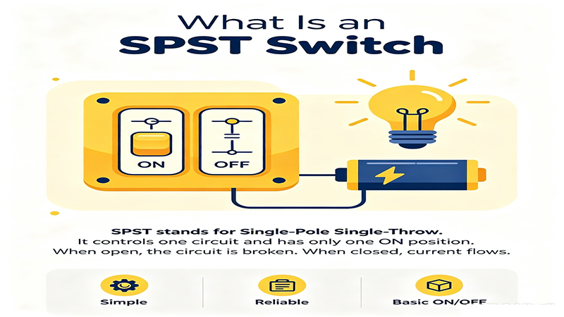
SPST
|
1
|
1
|
Simple ON/OFF control
|
|
SPDT
|
1
|
2
|
Selects one of two circuit paths
|
|
DPST
|
2
|
1
|
Turns two circuits ON/OFF together
|
|
DPDT
|
2
|
2
|
Controls two circuits and selects between two paths for each
|
A useful way to remember the difference is that an SPDT switch controls one circuit between two paths, while a DPDT switch performs the same operation for two circuits simultaneously.
How to Choose the Right DPDT Switch
Selecting a DPDT switch requires more than choosing the correct pole and throw configuration. The electrical and mechanical specifications must match the requirements of the application.
Voltage Rating
The switch must be rated for the operating voltage of the circuit. DC and AC ratings may differ significantly because interrupting DC current can produce more persistent electrical arcing.
Current Rating
The contact current rating must exceed the expected load current. Motors, solenoids, and other inductive loads can generate high inrush current, so the switch should be selected with adequate safety margin.
Contact Resistance
Low contact resistance is important when minimizing voltage drop, power loss, and signal degradation. This is especially relevant in low-voltage and precision electronic circuits.
Switching Life
Mechanical and electrical life ratings indicate how many switching operations the component can perform under specified conditions.
Mounting Style
Common mounting options include panel mount, PCB mount, chassis mount, and DIN rail configurations. The installation method should match the mechanical design of the equipment.
Actuator Type
DPDT switches are available as toggle switches, rocker switches, slide switches, push-button switches, rotary switches, and relay contacts.
Important Design Considerations
Although a DPDT switch is mechanically simple, proper circuit design is essential for reliable operation.
-
Verify the terminal arrangement using the manufacturer's datasheet.
-
Check voltage and current ratings for the specific load.
-
Consider inrush current when switching motors or capacitive loads.
-
Use appropriate suppression circuits for inductive loads when necessary.
-
Confirm whether break-before-make or make-before-break operation is required.
-
Ensure the switch provides sufficient mechanical life for the expected duty cycle.
-
Use suitable insulation, wiring, and enclosure protection for the operating environment.
Common DPDT Switch Problems and Troubleshooting
Intermittent Connection
Intermittent operation may be caused by worn contacts, oxidation, contamination, insufficient contact pressure, or mechanical damage.
Excessive Heating
If a switch becomes hot during operation, it may be carrying more current than its rated capacity or may have developed high contact resistance.
Incorrect Switching Function
An incorrectly wired DPDT switch can cause unexpected circuit behavior. Always identify the common and throw terminals before final installation.
Motor Does Not Reverse
If a DPDT switch is being used for motor reversal and the motor rotates in only one direction, check the crossed wiring arrangement, terminal identification, power supply, and switch contact continuity.
DPDT Switches in Modern Electronic Systems
Although semiconductor switching technologies such as transistors, MOSFETs, and integrated circuits are widely used in modern electronics, mechanical DPDT switches remain important. They provide physical isolation, straightforward operation, low standby power consumption, and intuitive manual control.
DPDT switching functionality can also be implemented using relays, contactors, and electronically controlled switching systems. In these cases, the same fundamental concept applies: two poles change between two possible connection states in a coordinated manner.
Frequently Asked Questions About DPDT Switches
What does DPDT stand for?
DPDT stands for Double Pole Double Throw. It describes a switch with two independent poles, each capable of connecting to one of two possible terminals.
How many terminals does a typical DPDT switch have?
A typical DPDT switch has six terminals: two common terminals and four throw terminals. However, additional terminals may exist for features such as illumination, grounding, or special mechanical configurations.
Can a DPDT switch reverse a DC motor?
Yes. A properly wired DPDT switch can reverse the polarity applied to a DC motor, causing the motor to rotate in the opposite direction.
Is a DPDT switch the same as two SPDT switches?
Functionally, a DPDT switch can be considered similar to two SPDT switches that are mechanically linked so both operate at the same time.
Can a DPDT switch control two separate circuits?
Yes. The two poles can control electrically separate circuits while being operated by the same mechanical actuator.
Conclusion
Understanding the mechanics of a DPDT switch in electronic circuits provides a solid foundation for designing reliable switching systems. The combination of two poles and two throws allows a DPDT switch to perform coordinated changes in multiple electrical paths with a single mechanical action.
From reversing DC motors and controlling actuators to routing signals and selecting operating modes, DPDT switches offer a simple and effective solution for many electronic and electrical applications. When selecting a DPDT switch, engineers should consider terminal configuration, voltage rating, current capacity, contact type, switching sequence, mechanical life, and the requirements of the connected load.
By understanding how the internal contacts move and how the poles and throws interact, it becomes much easier to wire, troubleshoot, and apply DPDT switches correctly in practical electronic circuits.