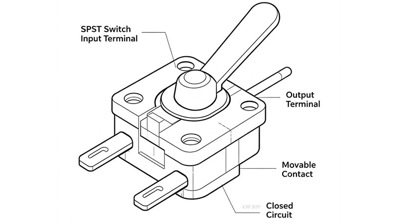
What Is an SPST Switch?
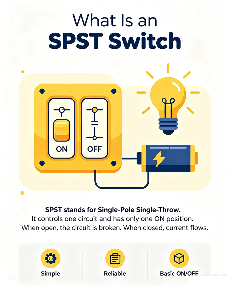
SPST stands for Single Pole Single Throw. It is one of the simplest switch configurations available. An SPST switch controls a single electrical circuit and has one switching path that can either be open or closed.
In a basic SPST switch, the two terminals are connected when the switch is in the ON position and disconnected when it is in the OFF position. Because of this simple structure, SPST switches are widely used for basic power control, circuit activation, and signal switching applications.
Key point: An SPST switch controls one circuit and provides a simple ON/OFF switching function. It is ideal when only one electrical path needs to be controlled.
How Does an SPST Switch Work?
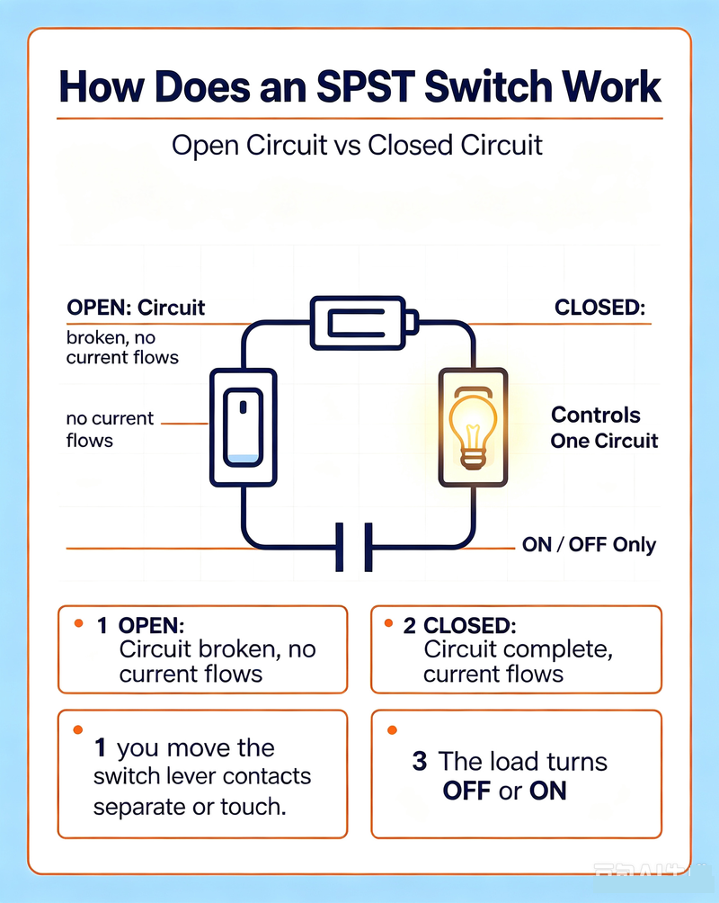
The operating principle of an SPST switch is straightforward. When the switch is closed, current can flow through the circuit. When the switch is open, the circuit is interrupted and current stops flowing.
SPST switches can be implemented as normally open or normally closed devices depending on the required circuit behavior. Mechanical toggle switches, push buttons, rocker switches, and certain electronic switching devices can all use an SPST configuration.
What Is a DPDT Switch?
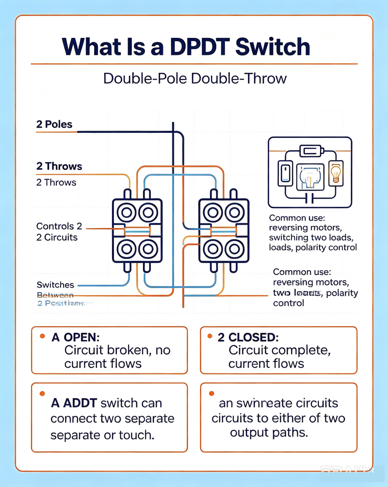
DPDT stands for Double Pole Double Throw. Unlike an SPST switch, a DPDT switch contains two poles and two possible switching positions for each pole. This allows the device to control two independent circuits or route signals between different paths.
A typical DPDT switch has six terminals. Depending on the switch position, each common terminal can be connected to one of two corresponding terminals. This makes DPDT switches significantly more flexible than SPST switches.
Key point: A DPDT switch can control two circuits simultaneously and can change the connection between multiple signal or power paths.
How Does a DPDT Switch Work?
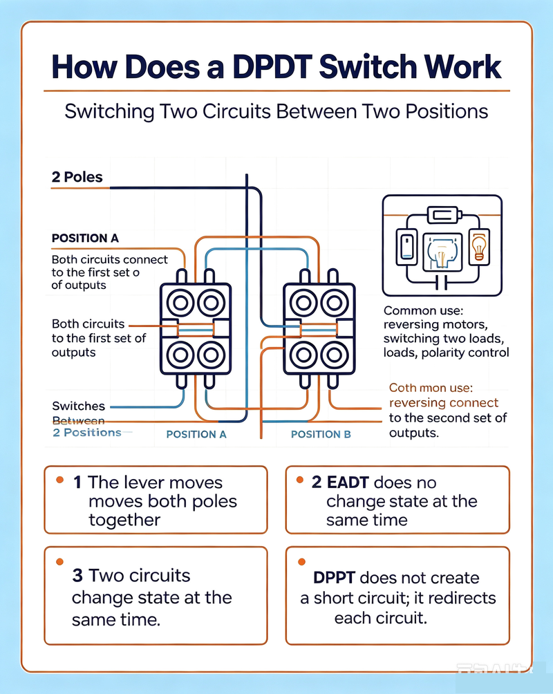
A DPDT switch normally contains two electrically separate switching sections that operate together. Each section has one common terminal and two selectable terminals.
In one switch position, the common terminals are connected to the first set of outputs. In the second position, they are connected to the other set. This arrangement can be used for circuit selection, polarity reversal, motor direction control, and signal routing.
SPST Switch vs. DPDT Switch: Configuration Comparison
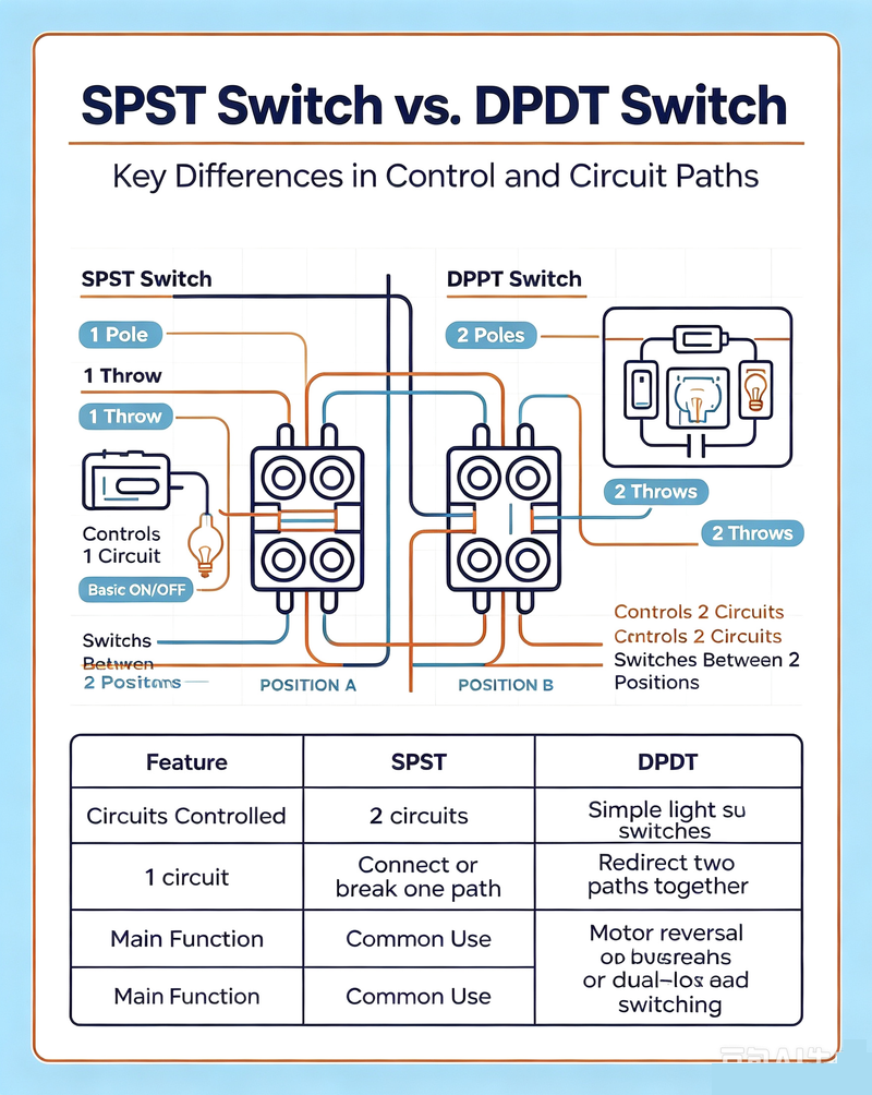
The main difference between SPST and DPDT switches is their number of poles and throws. The pole represents the number of independent circuits being controlled, while the throw represents the number of selectable connections for each pole.
|
Feature
|
SPST Switch
|
DPDT Switch
|
|
Full Name
|
Single Pole Single Throw
|
Double Pole Double Throw
|
|
Poles
|
1
|
2
|
|
Throws
|
1
|
2
|
|
Typical Terminals
|
2
|
6
|
|
Basic Function
|
ON/OFF control
|
Two-way circuit or signal routing
|
|
Circuit Complexity
|
Simple
|
More complex
|
|
Typical Applications
|
Power control, basic circuit activation
|
Signal routing, polarity reversal, motor control
|
|
Control Flexibility
|
Low
|
High
|
SPST vs. DPDT: Electrical Function
SPST Electrical Function
An SPST switch provides a straightforward connection or disconnection between two terminals. It is commonly used when a circuit only requires an ON/OFF function.
-
One controlled circuit
-
One switching path
-
Simple electrical design
-
Easy to install and troubleshoot
DPDT Electrical Function
A DPDT switch provides two independent poles, each capable of switching between two terminals. The two poles can operate together to perform more advanced circuit-routing functions.
-
Two controlled circuits
-
Two switching positions
-
Multiple signal paths
-
Suitable for circuit reversal and routing
SPST Switch Applications
SPST switches are commonly selected for applications where circuit simplicity and reliable ON/OFF control are the primary requirements.
-
Power supply ON/OFF control
-
Lighting systems
-
Electronic equipment power switches
-
Control panels
-
Industrial control circuits
-
Alarm and monitoring systems
-
Battery-powered equipment
-
Basic electrical test equipment
In low-complexity systems, an SPST switch can reduce wiring requirements and simplify maintenance. It is often the preferred choice when there is no need to select between multiple circuits.
DPDT Switch Applications
DPDT switches are useful when a system needs to control two circuits or switch between two alternative connection states.
-
DC motor forward and reverse control
-
Polarity reversal
-
Audio signal routing
-
Communication system signal selection
-
Power source selection
-
Industrial automation systems
-
Test and measurement equipment
-
Electronic switching circuits
For example, a DPDT switch can reverse the polarity applied to a DC motor. Changing the polarity changes the direction of motor rotation, making the DPDT configuration useful for simple forward/reverse motor controllers.
SPST vs. DPDT in RF and Microwave Applications
In RF and microwave systems, switch terminology becomes particularly important because the number of poles and throws describes how RF signal paths can be controlled. However, an RF switch must also be evaluated using high-frequency specifications such as insertion loss, isolation, return loss, switching speed, power handling, and operating frequency.
An RF SPST switch is generally used to connect or disconnect a single RF signal path. An RF DPDT switch can route two signal paths between different connections, depending on its internal architecture.
Important: A general-purpose electrical SPST or DPDT switch should not automatically be used in an RF system. RF applications require switches specifically designed for the intended frequency range, impedance, power level, and isolation requirements.
Important RF Switch Specifications
-
Frequency range: Determines the frequencies over which the switch maintains acceptable RF performance.
-
Insertion loss: Measures the signal power lost when the switch is in the ON state.
-
Isolation: Indicates how effectively the switch prevents unwanted signal leakage through an OFF path.
-
Return loss: Indicates the amount of reflected RF power caused by impedance mismatch.
-
Power handling: Defines the maximum RF power the switch can safely handle.
-
Switching speed: Important for automated test systems, communications, radar, and other fast-switching applications.
SPST vs. DPDT: Advantages and Disadvantages
Advantages of SPST Switches
-
Simple construction and operation
-
Low wiring complexity
-
Easy circuit integration
-
Simple troubleshooting
-
Suitable for basic ON/OFF applications
-
Usually cost-effective for simple designs
Disadvantages of SPST Switches
-
Limited switching functionality
-
Cannot independently route two circuits
-
Not suitable for applications requiring polarity reversal
-
Cannot directly provide two alternative switching paths
Advantages of DPDT Switches
-
Controls two circuits simultaneously
-
Provides multiple switching paths
-
Can be used for polarity reversal
-
Useful for motor direction control
-
Offers greater circuit flexibility
-
Suitable for more advanced signal-routing applications
Disadvantages of DPDT Switches
-
More terminals and wiring are required
-
More complex than SPST switches
-
Incorrect wiring can cause circuit faults
-
May require additional space in compact designs
How to Choose Between an SPST and DPDT Switch
Choosing between an SPST and DPDT switch depends primarily on the number of circuits and switching paths required by the application.
Choose an SPST Switch When:
-
You only need to turn one circuit ON or OFF.
-
The design requires a simple switching mechanism.
-
There is no need to select between two signal paths.
-
Space and wiring simplicity are important.
-
The application does not require polarity reversal.
Choose a DPDT Switch When:
-
Two circuits must be controlled simultaneously.
-
You need to switch between two connection states.
-
The application requires polarity reversal.
-
You need forward/reverse motor control.
-
You need more flexible signal routing.
How Switch Ratings Affect Selection
The SPST or DPDT configuration is only one part of switch selection. Electrical ratings must also match the requirements of the system.
Voltage Rating
The switch voltage rating must be equal to or greater than the maximum voltage present in the circuit. Exceeding the rated voltage can result in insulation failure, arcing, or premature switch damage.
Current Rating
The current rating determines how much current the switch contacts can safely carry. Loads with high inrush current, such as motors and capacitive loads, may require additional consideration beyond the nominal operating current.
RF Power Rating
For RF and microwave switches, power handling is frequency-dependent. Engineers should verify the manufacturer's maximum input power specifications across the actual operating frequency range rather than relying only on a general electrical current rating.
Frequency Rating
Conventional mechanical switches may not provide predictable performance at high RF frequencies. For microwave applications, use an RF-rated switch with specified impedance, insertion loss, isolation, and return loss.
SPST and DPDT Switches in Automated Test Systems
Automated test equipment often requires reliable switching between instruments, devices under test, antennas, and multiple signal paths. SPST switches can be used to enable or disable an individual path, while DPDT configurations can provide more complex routing functions.
In RF test systems, larger switching networks may use multiple SPST, SPDT, DPDT, SPnT, or matrix configurations to automate signal routing. The appropriate architecture depends on the number of RF ports, required isolation, switching speed, power handling, and measurement accuracy.
SPST vs. DPDT vs. SPDT
It is also useful to understand SPDT switches because SPDT is often confused with DPDT. SPDT means Single Pole Double Throw. It controls one circuit and switches that circuit between two possible paths.
|
Switch Type
|
Poles
|
Throws
|
Typical Function
|
|
SPST
|
1
|
1
|
ON/OFF control
|
|
SPDT
|
1
|
2
|
Selects one of two paths
|
|
DPDT
|
2
|
2
|
Controls two circuits and selects between two paths
|
In simple terms, an SPST switch is best for ON/OFF control, an SPDT switch is suitable for selecting between two paths, and a DPDT switch provides two SPDT functions that operate together.
Common Mistakes When Selecting an SPST or DPDT Switch
1. Choosing Based Only on Terminal Count
The number of terminals does not tell the entire story. Engineers should also verify voltage, current, frequency, power handling, contact configuration, environmental requirements, and mechanical life.
2. Ignoring Load Characteristics
Motors, relays, lamps, capacitive loads, and RF equipment can impose different electrical stresses on switch contacts. The switch should be selected according to the actual load characteristics.
3. Using a General-Purpose Switch for Microwave Signals
At high frequencies, parasitic capacitance and inductance can significantly affect signal integrity. RF applications require components designed and characterized for the operating frequency range.
4. Overlooking Isolation
In signal-routing systems, insufficient isolation can allow unwanted signals to leak into inactive paths. This can reduce measurement accuracy and system performance.
5. Ignoring Switching Life
Mechanical switches have finite contact life. Systems with frequent switching cycles may require a switch specifically rated for high mechanical or electrical endurance.
Frequently Asked Questions
Is an SPST switch better than a DPDT switch?
Neither configuration is universally better. An SPST switch is better for simple ON/OFF control, while a DPDT switch is better when two circuits or multiple switching paths must be controlled.
What is the main difference between SPST and DPDT?
SPST means Single Pole Single Throw and controls one circuit with one switching path. DPDT means Double Pole Double Throw and controls two poles, each with two selectable paths.
Can a DPDT switch replace an SPST switch?
A DPDT switch can often be wired to perform a simple ON/OFF function, but it may be unnecessary when only one circuit needs to be controlled. Using the simplest suitable configuration can reduce wiring and system complexity.
How many terminals does an SPST switch have?
A basic SPST switch typically has two terminals. However, physical switch packages can vary, particularly when additional poles, indicators, or auxiliary contacts are included.
How many terminals does a DPDT switch have?
A conventional DPDT switch typically has six terminals: two common terminals and two selectable terminals associated with each pole.
Can DPDT switches be used for RF applications?
Yes. RF DPDT switches are used for signal routing and other microwave applications, but the switch must be specifically designed for the required frequency, impedance, power level, insertion loss, isolation, and return loss.
Conclusion
The comparison between an SPST switch vs. DPDT switch comes down to switching requirements. An SPST switch provides a simple and reliable way to control one circuit, making it ideal for basic ON/OFF applications. A DPDT switch offers significantly greater flexibility by controlling two poles and providing two switching positions.
For electrical applications, consider voltage, current, load type, mechanical life, and installation requirements. For RF and microwave applications, additional specifications such as frequency range, insertion loss, isolation, return loss, switching speed, and RF power handling become critical.
By understanding the differences between SPST, SPDT, and DPDT configurations, engineers can select the appropriate switch architecture for power control, signal routing, industrial automation, communications, RF testing, and microwave systems.
Related Topics: SPST switch, DPDT switch, SPST vs DPDT, SPST switch vs DPDT switch, SPDT vs DPDT, RF switch, RF microwave switch, RF signal switch, electronic switch, coaxial RF switch, microwave switch, RF signal routing, DPDT switch applications, SPST switch applications.