

























Discover why high DC-RF isolation is critical in microwave bias tee design. Learn about performance impacts, design considerations, and best practices for RF engineers.
Sep 04 ,26


5G communication testing, wireless terminal automated testing
Aerospace communication systems
Precision measurement equipment, radio frequency signal control of radar transmitters
Communication and navigation systems
Optical communication module-related testing
Interconnection of wireless communication base stations
A bias tee is an important RF component used to inject DC power onto an RF transmission line while allowing high-frequency signals to travel on the same cable. In software-defined radio (SDR) systems, a bias tee is commonly used to power active antennas, low noise amplifiers (LNAs), GNSS antennas, satellite reception equipment, and other remote RF devices without requiring a separate power cable.
As SDR applications expand into satellite communications, ADS-B reception, spectrum monitoring, amateur radio, cellular analysis, GNSS, and scientific RF research, understanding how an SDR bias tee works is increasingly important. This guide explains the working principle, circuit structure, applications, specifications, benefits, limitations, and selection considerations of bias tees for SDR systems.

A bias tee is a three-port RF network that combines or separates direct current (DC) and radio-frequency (RF) signals. Its primary function is to send DC power and RF signals through the same coaxial cable while preventing the DC supply from interfering with sensitive RF equipment.
A typical bias tee has three connections:
In an SDR system, the bias tee is often integrated directly into the SDR hardware. When enabled through software or a device setting, the SDR sends a specified DC voltage to the antenna connector.
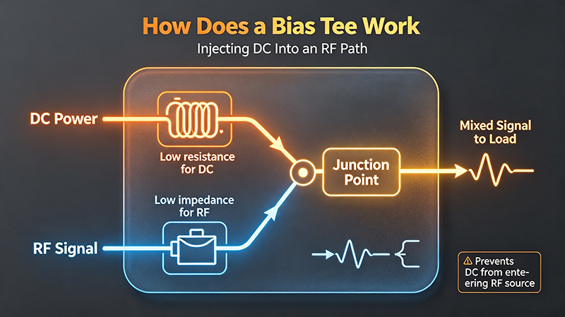
The operating principle of a bias tee is based on the different behavior of inductors and capacitors at DC and RF frequencies.
A basic bias tee uses an inductor in the DC path and a capacitor in the RF path. The inductor allows DC current to reach the remote device but presents a high impedance to RF signals. The capacitor allows RF signals to pass while blocking DC voltage from reaching the SDR's sensitive RF circuitry.
This arrangement makes it possible to transmit power and RF signals over one coaxial cable. The remote device receives DC power and processes or amplifies the RF signal, while the SDR receives the RF signal with the DC component blocked.
Many SDR installations use antennas and RF components located far away from the receiver. Running a separate power cable to each device increases installation complexity and may create additional grounding or electromagnetic interference problems.
A bias tee simplifies the system by allowing one coaxial cable to perform two functions:
A single coaxial cable can replace separate RF and DC wiring, reducing installation complexity and improving system organization.
An LNA can be installed close to the antenna, amplifying weak signals before they travel through a long coaxial cable.
Properly powered active antennas and LNAs can significantly improve the reception of weak RF signals in many SDR applications.
Bias tees provide a convenient method for powering remote RF devices without installing an additional power source.
The impedance of an inductor increases with frequency, while the impedance of a capacitor decreases as frequency increases. This frequency-dependent behavior allows the bias tee to separate DC and RF signals.
Where:
At DC, the frequency is effectively zero. An ideal capacitor blocks DC, while an inductor allows DC to pass. At RF frequencies, the inductor presents a high impedance that prevents RF signals from entering the power supply, while the capacitor presents a lower impedance that allows RF signals to pass through the signal path.
Many active antennas contain an integrated amplifier. These antennas require DC power to operate, and an SDR bias tee can deliver the required voltage through the coaxial cable.
LNAs are widely used in SDR receiving systems to improve weak-signal reception. Placing an LNA near the antenna can compensate for cable loss and improve the effective system sensitivity.
Active GNSS antennas often include a low noise amplifier that requires DC power. A compatible bias tee can provide the required voltage through the antenna feed line.
Bias tees are frequently used in satellite SDR systems where external LNAs, active antennas, or specialized front-end equipment require DC power.
For 1090 MHz ADS-B reception, a low noise amplifier installed close to the antenna may improve weak aircraft signal reception, especially when long coaxial cables are used.
Bias tees are useful for RF laboratories, spectrum monitoring, amateur radio projects, antenna testing, and experimental receiver systems that require remote DC-powered RF devices.
SDR users can choose between an integrated bias tee built into the SDR device and an external bias tee installed separately in the RF signal path.
| Feature | Integrated SDR Bias Tee | External Bias Tee |
|---|---|---|
| Installation | Simple and compact | Requires an additional RF component |
| Power Source | Provided by the SDR | Usually uses an external DC supply |
| Voltage Flexibility | Often fixed or limited | Can support different external voltages |
| Current Capability | May be limited | Can support higher-current applications |
| RF Frequency Range | Depends on SDR design | Can be selected for specific RF bands |
| Protection | May include built-in protection | Depends on the external bias tee design |
Not all bias tees are suitable for every SDR application. Engineers and SDR users should evaluate the following specifications before selecting a bias tee.
The bias tee must support the operating frequency range of the SDR system. For example, a bias tee designed for low-frequency HF applications may not perform correctly at several gigahertz.
Check the voltage required by the active antenna or RF device. Common bias tee voltages include 3.3 V, 5 V, 9 V, 12 V, and higher values for specialized equipment.
The bias tee and SDR must provide sufficient current for the connected device. Exceeding the current rating can damage the SDR, bias tee, power supply, or remote RF equipment.
Low insertion loss is important because the bias tee is inserted into the RF signal path. Excessive insertion loss can reduce received signal strength and degrade system performance.
A good RF bias tee should maintain proper impedance matching, typically 50 ohms in many SDR and microwave systems. Poor matching can cause signal reflections and reduce performance.
RF isolation between the DC and RF ports is important to prevent RF energy from entering the power supply and causing interference or unwanted signal leakage.
Common connector options include SMA, N-type, BNC, F-type, and other coaxial interfaces. The connector must be compatible with the SDR, coaxial cable, and antenna system.
The exact procedure depends on the SDR hardware and software platform. In many SDR devices, the bias tee can be enabled through a software setting, driver command, or hardware configuration.
Choosing the correct SDR bias tee requires matching both the RF and DC requirements of the complete system.
One of the most common SDR configurations combines a bias tee with a low noise amplifier. For best results, the LNA is often installed as close to the antenna as practical.
The basic signal chain is:
This configuration is useful because coaxial cable loss occurs before the SDR receiver. If the signal is very weak, placing the LNA near the SDR may not fully compensate for signal loss that has already occurred in a long antenna cable.
By placing the LNA close to the antenna, the weak signal is amplified before experiencing significant cable attenuation. The bias tee then supplies power to the remote LNA through the same coaxial cable.
Possible causes include a disabled SDR bias tee, incorrect software configuration, insufficient supply voltage, a damaged coaxial cable, excessive current demand, or an incompatible external component.
Check the bias tee insertion loss, cable quality, LNA gain, antenna placement, power supply noise, and possible RF interference. A noisy DC supply can introduce unwanted interference into the RF system.
This may indicate a short circuit or excessive current draw. Disable the bias tee immediately and inspect the cable, connectors, and remote device.
Adding an LNA does not always improve reception. In environments with strong transmitters, excessive gain can overload the SDR receiver. A suitable band-pass or notch filter may be required.
Always verify the signal path before enabling the bias tee. If multiple RF components are connected, make sure all devices between the bias tee and the remote load are designed to pass or block DC as required.
A bias tee itself does not amplify RF signals. Its primary function is to inject DC power onto the RF cable. However, it can indirectly improve SDR reception by enabling the use of active antennas and low noise amplifiers.
The actual performance improvement depends on several factors:
In weak-signal applications with significant feedline loss, a properly designed active front end powered through a bias tee can provide substantial system-level benefits.
Although a bias tee is a relatively simple RF component, incorrect use can damage expensive equipment. Follow these precautions:
A bias tee and a DC block are related RF components, but they perform different functions.
| Component | Main Function | DC Transmission | RF Transmission |
|---|---|---|---|
| Bias Tee | Combines or separates DC and RF | Controlled DC path | Yes |
| DC Block | Prevents DC from passing | No | Yes |
A DC block may be used to protect equipment from unwanted DC voltage, while a bias tee is used when DC power must intentionally travel along the RF transmission line.
A bias tee injects DC power onto the SDR antenna coaxial cable while allowing RF signals to pass between the antenna system and the SDR receiver.
Yes, provided the LNA is designed to receive the correct DC voltage through its RF coaxial connection and the bias tee can provide sufficient voltage and current.
No. A bias tee is not an amplifier. It supplies DC power through an RF cable and may be used to power an external LNA or active antenna.
Yes. A short circuit, excessive current draw, incorrect external voltage, or improper connection can potentially damage SDR hardware. Always follow the device specifications.
The voltage depends on the SDR model. Common values include 3.3 V and 5 V, while external bias tees can support other voltage levels depending on their design.
No. A bias tee is only necessary when a remote RF component, such as an active antenna or LNA, needs DC power delivered through the coaxial cable.
Understanding the bias tee in SDR systems is essential for building efficient and reliable RF receiving and testing setups. A bias tee allows DC power and RF signals to share the same coaxial cable, making it possible to power active antennas, low noise amplifiers, GNSS antennas, and other remote RF devices without installing separate power wiring.
When selecting an SDR bias tee, pay close attention to frequency range, DC voltage, maximum current, insertion loss, impedance, RF isolation, connector type, and protection features. A correctly selected bias tee can simplify installation and support improved system performance when used with properly designed active RF components.
Whether you are building an SDR receiver for satellite communication, ADS-B monitoring, GNSS reception, spectrum analysis, amateur radio, or laboratory testing, understanding how a bias tee works will help you design a safer and more effective RF signal chain.
High-tech Enterprise, Feifeng Talent
Chief Engineer Wang graduated with a master's degree in high-power microwave from the Institute of Electronics, University of Chinese Academy of Sciences.
View Full Profile