

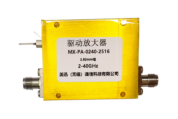



Directional couplers explained — what they are, how they work, the main types, key specifications, and the most common applications in RF, microwave, and test systems.
Sep 02 ,26


5G communication testing, wireless terminal automated testing
Aerospace communication systems
Precision measurement equipment, radio frequency signal control of radar transmitters
Communication and navigation systems
Optical communication module-related testing
Interconnection of wireless communication base stations
A dual directional coupler is a four-port passive microwave component that samples power traveling in both the forward and reverse directions of a transmission line at the same time. Because it replaces two separate directional couplers with one matched device, it simplifies RF board layout, reduces cost, and guarantees consistent forward and reverse coupling performance. This guide walks through the working principle, coupling factor, directivity, major construction types, design rules, and selection criteria that engineers need to specify the correct part.
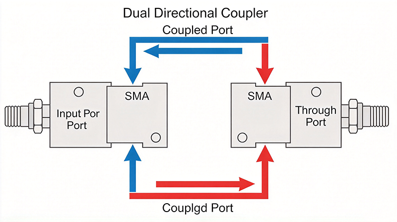
A dual directional coupler is a passive four-port RF network used to measure or sample power traveling along a transmission line in both directions simultaneously. Unlike a two-port directional coupler, which senses only one direction, the dual version exposes separate forward and reverse sampling outputs from a single physical structure.
The typical port arrangement is as follows:
Because ports 3 and 4 respond to opposite directions, a dual directional coupler can measure both the forward signal and the reflected signal without switching instruments or physically reversing the device. This is the core reason engineers choose a dual coupler over two separate single directional couplers.
Every practical dual directional coupler is a reciprocal passive network. It contains no active elements, requires no DC power, and introduces only a defined insertion loss and phase shift on the through path. Typical implementations are built as parallel stripline, microstrip, suspended stripline, lumped-element, or waveguide structures.
Because the forward and reverse responses are available at the same time, dual directional couplers appear wherever a system needs simultaneous knowledge of incident and reflected power:
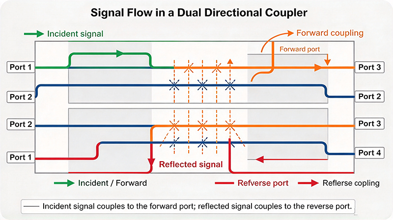
The operating principle of a dual directional coupler is the same as that of a single directional coupler: a portion of the RF energy on the main transmission line is transferred by constructive and destructive interference into a secondary path, and the amplitude and phase of the coupled signal depends on the direction of travel.
When power travels from the input port toward the through port, the coupled port associated with that direction receives a defined fraction of the power. The ratio of input power to forward coupled power is the coupling factor, expressed in decibels.
A coupling factor of 6 dB corresponds to 25 percent of the input power; 10 dB corresponds to 10 percent; 20 dB corresponds to 1 percent. A dual directional coupler is symmetric: the forward coupled port sees a nominal coupling factor C, and the reverse coupled port also sees the same nominal coupling factor C when power reverses.
When power travels in the opposite direction, an ideal network would deliver zero power to the forward coupled port. In reality, some signal leaks across. Directivity quantifies how well the network rejects this leakage.
Directivity is always specified as a positive number. A high directivity of 30 dB means the forward port suppresses opposite-direction energy by a factor of 1000. Directivity is what makes a dual directional coupler useful for reflectometry: without it, the reverse reading would be corrupted by feedthrough of the incident signal.
The through path is not lossless. Power is removed by the coupling structures, so the through path always shows some insertion loss. In addition, a dual directional coupler should exhibit amplitude balance and phase balance: the forward and reverse couplings should have nearly identical magnitude and a well-defined phase relationship to each other.
High-quality dual directional couplers maintain amplitude balance within a few tenths of a dB and phase balance within a few degrees across the operating band. This balance matters when the two coupled ports are subtracted or summed to extract a reflection coefficient.
Dual directional couplers are classified by the transmission line structure used to create the coupling. The physical structure determines frequency range, power handling, directivity, and cost.
The branch-line coupler, also called a hybrid coupler, uses quarter-wave shunt and series branches to create two matched paths. A dual version combines two branch-line sections so both directions are sampled. It offers excellent directivity and wide bandwidth, often 10 to 20 percent of center frequency, and is a standard choice for 3 dB and 6 dB couplings in stripline and waveguide.
The Lange coupler uses interdigitated coupled lines to achieve very wide bandwidth, sometimes more than 50 percent of center frequency. It is the classic structure for 3 dB and 6 dB wideband couplers in microstrip, and it is widely used in balanced mixers and broadband receiver front ends. Lange couplers are popular where a single dual directional coupler must cover an octave.
A Wilkinson-based dual directional coupler inserts an isolation resistor between two divider outputs, then couples from both sides. Because the isolation resistor suppresses cross-coupling, the directivity is usually very high, often above 25 dB. This structure is common for high-directivity broadband applications.
Edge-coupled microstrip couplers are the lowest cost approach. A section of microstrip runs parallel to the main line over a shared dielectric, and power transfers through the fringing field. Bandwidth is limited by coupling strength, typically 10 to 20 percent, and directivity is lower, often 15 to 22 dB. This is a common choice for cost-sensitive sub-1 GHz designs.
In suspended stripline, the center conductor is suspended between two ground planes, which increases power handling and reduces dielectric loss. Waveguide dual directional couplers use aperture or probe coupling in a waveguide run and are used from 1 GHz up to over 100 GHz in radar, satellite, and high-power applications. Waveguide couplers can handle kilowatt-level peaks with very high directivity.
| Type | Typical Frequency | Directivity | Power Handling | Relative Cost |
|---|---|---|---|---|
| Branch-line hybrid | 1 – 40 GHz | 25 – 40 dB | Low to moderate | Moderate |
| Lange interdigitated | 1 – 50 GHz | 20 – 35 dB | Low | Moderate |
| Wilkinson-based | DC – 18 GHz | 25 – 35 dB | Low to moderate | Low |
| Edge-coupled microstrip | 200 MHz – 6 GHz | 15 – 22 dB | Very low (1 – 5 W) | Very low |
| Suspended stripline | 1 – 40 GHz | 25 – 40 dB | High (100 – 500 W) | High |
| Waveguide aperture | 1 – 110 GHz | 30 – 45 dB | Very high (kW peak) | High |
| Lumped element (LTCC) | 300 MHz – 6 GHz | 15 – 25 dB | Very low | Low (high volume) |
Engineers evaluate a dual directional coupler using a defined set of parameters. The following table explains what each parameter means and why it matters during selection.
| Parameter | What It Means | Why It Matters |
|---|---|---|
| Coupling factor | Ratio of coupled port power to input power in dB | Determines how strongly the main line is sampled and how much signal is available at the detector |
| Directivity | Suppression of opposite-direction signal at the coupled port | Determines accuracy of reflection and reverse power measurements |
| Insertion loss | Loss from the input port to the through port | Reduces signal level in the signal path; must be budgeted in the link loss calculation |
| Return loss | Impedance match quality at each port | Poor return loss creates reflections that corrupt measurement |
| VSWR | Derived from return loss | Quick indicator of impedance match across the band |
| Amplitude balance | Difference between forward and reverse coupling magnitude | Must be small when the two ports are compared or subtracted |
| Phase balance | Phase difference between forward and reverse outputs | Critical for quadrature and differential architectures |
| Frequency range | Band over which all parameters are specified | Must cover the intended operating band with margin |
| Power handling | Maximum continuous and peak input power | Limits transmitter monitoring and high-power test applications |
| Operating temperature | Temperature range for rated performance | Performance drifts outside the reference temperature |
The distinction between a dual and single directional coupler is the number of coupled ports, but the practical consequences reach board area, cost, calibration, and measurement confidence.
| Aspect | Single Directional Coupler | Dual Directional Coupler |
|---|---|---|
| Number of ports | 3 (input, through, coupled) | 4 (input, through, forward coupled, reverse coupled) |
| Directions sensed | One, depending on orientation | Both, simultaneously |
| Board area | Two devices needed for bidirectional sensing | One device |
| Cost | Higher total cost for bidirectional setups | Lower total cost |
| Amplitude matching between directions | Not guaranteed across separate devices | Guaranteed by design and calibration |
| Calibration effort | Two calibration procedures | Single calibration covers both directions |
| Layout symmetry | Requires mirrored placement | Symmetric by construction |
The primary caveat is that a dual directional coupler is characterized as one matched four-port device. Two separate single couplers, even from the same lot, will generally show more variation between forward and reverse coupling factors. For precision reflectometry, that difference matters. For simple power monitoring, it usually does not.
Choosing the right coupling factor is the single most important decision when specifying a dual directional coupler. The coupling factor sets both how much signal is available at the detector and how strongly the main line is loaded.
Samples 50 percent of the power. Almost never used as a measurement coupler because it removes half the signal from the main line. Used in power dividers, 4-port hybrids, and I/Q generation networks.
Samples 25 percent of the power. Common in power monitoring and leveling loops where high sensitivity is required. Places moderate burden on the through path.
Samples 10 percent of the power. The most widely used value for general-purpose monitoring and measurement, offering a good compromise between sensitivity and main-line disturbance.
Samples about 2.5 percent of the power. Used where the main line must be minimally perturbed, such as in front of a high-power amplifier output.
Samples 1 percent of the power. Preferred for high-power monitoring and for wide dynamic range measurement after a power amplifier.
Samples 0.1 percent or less. Used in probe stations and high-power tap applications where disturbance must be negligible. Requires a sensitive detector.
The relative geometry of the two coupled ports defines the phase relationship between the forward and reverse responses, which in turn determines how the signals can be used downstream.
In a 90-degree dual directional coupler, the forward coupled port sits 90 degrees apart from the reverse coupled port. The two outputs are therefore in quadrature, meaning a phase difference of 90 degrees between them. This arrangement allows the forward and reverse signals to be combined directly to produce an I/Q pair, or summed to extract magnitude without cancellation.
Quadrature dual directional couplers are the standard choice for vector network analyzers and for coherent I/Q receiver architectures where phase accuracy between channels directly affects measurement fidelity.
In a 180-degree dual directional coupler, the two coupled ports are positioned in opposite phase. When both ports carry equal signals, they cancel. This is useful in push-pull amplifier networks, differential measurement setups, and self-cancelling mixers where the physical symmetry of the structure improves rejection of common-mode effects.
Some manufacturers offer a broadband or octave dual directional coupler whose two coupled ports maintain a well-defined relationship across a full octave or more. These are typically implemented as Lange structures and are specified with phase balance and amplitude balance parameters in addition to the standard coupling factor and directivity.
Whether you are designing a dual directional coupler from scratch or specifying an off-the-shelf part, the following parameters determine performance and must be evaluated together.
Coupling factor and directivity both degrade away from the design center frequency. A coupler specified for 10 to 20 GHz may have significant roll-off at 20.5 GHz. Always verify the full parameter set across the band you intend to use, not just at the center frequency. Ultra-wideband requirements typically push you toward Lange structures, while narrowband high-directivity requirements favor branch-line or waveguide structures.
The substrate dielectric constant and loss tangent directly determine coupling behavior and directivity. Low-loss substrates such as Rogers RO3003, RO4003C, or RO4350B are standard for microwave couplers. High dielectric constant materials allow tighter spacing but shift the design center frequency. The loss tangent matters most at high frequencies, where dielectric loss reduces directivity and increases insertion loss.
Thin microstrip conductors limit power handling to a few watts because of current density and dielectric heating. Stripline and suspended stripline with wide center conductors handle far more. For continuous power above roughly 50 W in continuous-wave systems, suspended stripline or waveguide structures are usually the correct choice.
All unused ports must be terminated in the characteristic impedance, which is 50 ohms for single-ended systems. An open or mismatched coupled port reflects energy back into the coupler, degrading directivity, insertion loss, and port match. Use precision 50 ohm load resistors or absorptive loads, and place them close to the coupler to minimize added interconnect loss.
Coupler performance degrades quickly if the layout is careless. Keep the coupled lines physically parallel and of matched length. Maintain via stitching every lambda over twenty along ground planes to suppress parallel-plate and substrate modes. Keep connector launches short, and keep the RF path over continuous ground. Above roughly 3 GHz, solder mask and solder thickness become non-negligible contributors to coupling error and should be accounted for in simulation.
Coupling factor and directivity are temperature-dependent parameters because dielectric constant and conductor resistance both change with temperature. For critical applications, specify the operating temperature range and require the coupler to meet its parameters across that range, not merely at 25 degrees Celsius.
The mechanical and electrical construction of a dual directional coupler determines its cost, size, power handling, and performance ceiling. The main options are described below.
| Technology | Frequency Ceiling | Size | Key Advantage | Key Limitation |
|---|---|---|---|---|
| Microstrip | Up to about 6 GHz | Very small | Lowest cost, easy to fabricate | Low power handling, lower directivity |
| Stripline | Up to about 40 GHz | Small | Good directivity, better power handling | Requires multilayer fabrication |
| Suspended stripline | Up to about 40 GHz | Larger | High power handling, low loss | More expensive, more complex assembly |
| LTCC / lumped element | Up to about 6 GHz | Extremely small | Excellent for high-volume miniaturization | Limited power and temperature range |
| Waveguide | 1 GHz to over 110 GHz | Large | Highest power and directivity | Bulky, narrow band per section |
| Machined block | Up to about 67 GHz | Medium | Tight tolerances, high precision | Cost scales poorly below 10 GHz |
The primary application of the dual directional coupler is in network analyzers, where it serves as the directional detector at the end of the test port. Because both directions are captured simultaneously and simultaneously calibrated, a single coupler supports full two-port S-parameter measurement including return loss, insertion loss, and isolation. Modern analyzers often use multiple dual directional couplers in an N-port configuration.
In a transmitter chain, a dual directional coupler ahead of the antenna or load provides forward power for a power-level indicator and reverse power for reflected power monitoring. Operators can then detect excessive VSWR, antenna mismatch, or a failing load before damage occurs. In closed-loop operation, the forward coupled signal feeds an AGC or power control loop.
At the input of a receiver, a weak-coupled dual directional coupler measures total received power. Because the reverse port also responds to transmitter leakage entering through the antenna, the receiver chain can distinguish legitimate signal power from self-transmitted leakage, which improves AGC accuracy and protects the front end from desensitization.
Time-domain reflectometry and related sensing techniques rely on separating the incident wave from the reflected wave. The forward coupled port provides the reference, and the reverse coupled port provides the reflection. Dividing the two yields a reflection coefficient that can be converted into material properties such as moisture content, density, or liquid level.
Radar receivers and electronic warfare systems need accurate forward and reverse power for duplexer analysis, antenna reflection measurement, and jammer detection. High-power waveguide and suspended stripline dual directional couplers are common in these applications because they tolerate kilowatt-level peak power.
Satellite ground stations use dual directional couplers in the feed chain for uplink power monitoring and for pilot-tone level control. In 5G and 6G radio units, compact stripline and LTCC dual directional couplers support per-element transmit power monitoring and closed-loop power control in massive MIMO arrays.
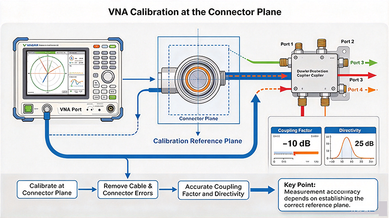
Accurate characterization of a dual directional coupler requires a vector network analyzer and a well-defined measurement setup.
A four-port VNA is the natural tool. Measure the full S-parameter matrix, then derive:
In simpler practical terms, forward coupling is the difference between the through path and the forward coupled path, corrected for mismatch. Directivity is obtained from the reverse coupled response with the ports properly terminated. Return loss and VSWR come directly from the reflection coefficients.
For production test, two independent power meters connected to the forward and reverse coupled ports are usually sufficient. Record the power at each port, apply the calibration factors, and compute coupling factor and directivity. This method is fast and inexpensive but does not reveal phase information.
Systematic selection avoids the most common sourcing mistakes. Follow this sequence.
When a dual directional coupler does not behave as expected, the cause is usually one of a small number of predictable issues.
Poor directivity almost always comes from an unterminated or mismatched coupled port. Check that every unused port is terminated with a precision 50 ohm load, and that the load is not connected through a long or bent cable. A second common cause is inadequate ground stitching, which allows substrate modes to leak between the coupled lines.
Excess loss usually indicates either a low-impedance substrate chosen for cost reasons or an improperly terminated port. Also verify that connector launches are not over-tightened, because microstrip edge transitions are easily damaged by mechanical strain.
Measurements that drift with time or temperature are usually caused by temperature-dependent behavior or by interconnect changes between calibration and test. Lock the calibration to the same temperature and avoid disconnecting and reconnecting cables after calibration.
Apparent reverse power that does not change with load may indicate directivity leakage rather than a genuine reflection. Verify directivity with the port properly terminated, and consider whether the frequency is outside the specified band, where directivity typically falls sharply.
Couplers with weak coupling, such as 20 dB or higher, can pick up spurious signals on the detector side. Keep detector traces short, shielded where appropriate, and terminated when not in use to prevent rectification of noise into a false reading.
A dual directional coupler provides forward and reverse power sampling from a single matched four-port device. That capability makes it the natural choice for network analyzers, transmitter monitoring, receiver AGC loops, reflectometry sensors, radar front ends, and satellite and 5G infrastructure. Choosing the correct part requires balancing four specifications together rather than in isolation: coupling factor, directivity, insertion loss, and power handling, evaluated across the full operating frequency band.
The construction type further narrows the options. Lange structures serve wideband and octave requirements, branch-line hybrids deliver high directivity in a narrow or moderate band, microstrip minimizes cost at low frequency, suspended stripline handles high power, and waveguide remains the only practical choice above 100 GHz and at kilowatt peak power levels. In every case, correct 50 ohm termination of the unused ports and disciplined ground stitching are non-negotiable.
For further technical reading, consult the IEEE Transactions on Microwave Theory and Techniques, the Microwave Journal, and application notes published by leading microwave component manufacturers. For datasheet-driven selection across manufacturers, the dbspecMW catalog provides parametric search over coupling factor, directivity, insertion loss, frequency range, and power handling.
Our engineering team can identify the optimal coupler topology for your frequency, power, directivity, and cost requirements, and provide parametric data across manufacturers.
Contact Our RF Engineers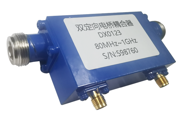
High-tech Enterprise, Feifeng Talent
Chief Engineer Wang graduated with a master's degree in high-power microwave from the Institute of Electronics, University of Chinese Academy of Sciences.
View Full Profile