

























Directional couplers explained — what they are, how they work, the main types, key specifications, and the most common applications in RF, microwave, and test systems.
Sep 02 ,26


5G communication testing, wireless terminal automated testing
Aerospace communication systems
Precision measurement equipment, radio frequency signal control of radar transmitters
Communication and navigation systems
Optical communication module-related testing
Interconnection of wireless communication base stations

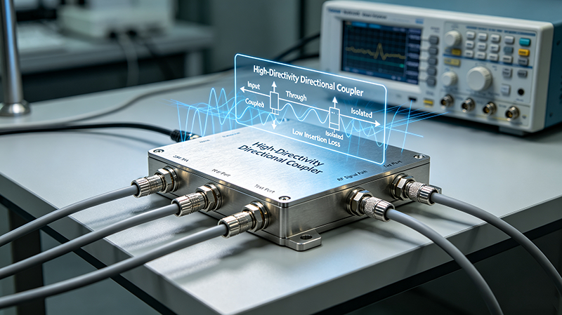
A directional coupler is a passive four-port RF or microwave device designed to transfer a controlled amount of electromagnetic energy from a primary transmission path to a secondary coupled path. Unlike a conventional power divider, a directional coupler is designed to provide a defined relationship between the input, through, coupled, and isolated ports.
Directional couplers are widely used in RF systems because they can sample a small portion of a signal without significantly disturbing the main transmission path. Depending on the design, they can operate across frequencies ranging from MHz to millimeter-wave bands.
Typical applications include RF power monitoring, signal measurement, antenna systems, radar, wireless communications, test equipment, feedback circuits, and microwave signal distribution.
A conventional directional coupler contains four ports:
Receives the RF or microwave signal entering the main transmission path.
Carries most of the input power toward the main system load.
Provides a controlled sample of the input or forward-traveling signal.
Ideally receives little or no power when the signal enters through the input port.
In a properly terminated directional coupler, the isolated port is normally terminated with a matched load. This prevents unwanted reflections from degrading the coupler's directional performance.
The working principle of a directional coupler is based on controlled electromagnetic coupling between two transmission paths. When an RF signal travels through the main transmission line, a portion of its electromagnetic energy is transferred to a nearby secondary transmission structure.
The physical geometry of the coupler determines how much energy is transferred and in which direction. Depending on the implementation, coupling can be achieved through electric fields, magnetic fields, or both.
For example, in a coupled-line directional coupler, two transmission lines are positioned close enough that electromagnetic fields from one line interact with the other. The resulting coupled signals have specific amplitude and phase relationships. By carefully controlling line spacing, length, substrate characteristics, impedance, and operating frequency, engineers can obtain the desired coupling factor and directivity.
The key feature is directionality. The coupled signal traveling in one direction reinforces at the coupled port, while signals traveling in the opposite direction tend to cancel because of their phase relationships. This allows the device to distinguish between forward and reflected power.
Selecting a directional coupler requires understanding several important RF specifications.
```The coupling factor indicates how much input power is transferred to the coupled port. It is normally expressed in decibels (dB):
For example, a 10 dB coupler ideally transfers approximately 10% of the input power to the coupled port, while a 20 dB coupler transfers approximately 1%.
Insertion loss represents the reduction in signal power between the input and through ports. Lower insertion loss is generally preferred because it minimizes the impact of the coupler on the main RF signal path.
Directivity describes the ability of the coupler to distinguish between forward and reverse traveling waves. It is closely related to the isolation between the coupled and isolated ports.
High directivity is particularly important for measuring reflected power and monitoring antenna or transmission-line mismatch.
Isolation indicates how effectively the isolated port is separated from the input port under the specified operating conditions. Higher isolation generally indicates better suppression of unwanted signal leakage.
Return loss and VSWR characterize impedance matching at the RF ports. A well-matched directional coupler reduces reflections and improves overall system performance.
The operating frequency range defines where the coupler meets its specified coupling, directivity, insertion loss, and matching requirements. Broadband and narrowband directional couplers are designed for different system requirements.
Power handling specifies the maximum RF power the directional coupler can safely process. High-power applications require careful consideration of conductor losses, dielectric heating, thermal management, and breakdown limits.
```Coupled-line designs use two transmission lines placed close together. They are commonly implemented using microstrip, stripline, or other planar transmission-line technologies and are widely used in RF and microwave circuits.
Waveguide directional couplers use electromagnetic coupling between waveguide structures. They are especially useful at microwave and millimeter-wave frequencies where waveguide transmission provides low-loss and high-power performance.
Cavity-based designs use resonant electromagnetic structures to achieve controlled coupling. They can provide high performance in applications requiring specific frequency characteristics.
A bi-directional coupler can be used to monitor both forward and reflected signals. These devices are useful in RF power monitoring, antenna systems, transmitter protection, and automatic control systems.
```Although directional couplers and power dividers can both distribute RF energy, they are designed for different purposes.
| Feature | Directional Coupler | Power Divider |
|---|---|---|
| Primary purpose | Signal sampling and directional monitoring | Splitting or combining RF power |
| Typical ports | Four | Three or more |
| Direction sensing | Yes | Generally no |
| Typical use | Power monitoring and measurement | Signal distribution |
A small signal sample can be sent to a detector or measurement instrument without interrupting the primary RF path.
Directional couplers help measure forward and reflected power and can support antenna matching and protection functions.
They are used for signal sampling, transmitter monitoring, calibration, and receiver test functions.
Directional couplers are used in base stations, RF front ends, distributed antenna systems, and signal distribution networks.
They provide controlled signal sampling for spectrum analyzers, network analyzers, power meters, and automated test systems.
A sampled RF signal can be used by control circuits to regulate transmitter output power and monitor system performance.
Choosing the right directional coupler requires matching its electrical and mechanical specifications to the RF system.
One of the most important advantages of a directional coupler is its ability to separate forward and reverse traveling waves. In a transmission system, part of the RF energy may be reflected because of impedance mismatch, antenna mismatch, cable problems, or an improperly terminated load.
A high-directivity coupler can distinguish the desired traveling wave from the reflected wave more accurately. This makes it valuable for measuring forward power, reflected power, return loss, and VSWR.
Poor directivity can introduce measurement errors because unwanted reverse-direction energy appears at the coupled port. Therefore, directivity should be evaluated alongside coupling accuracy when selecting a coupler for precision measurement.
RF engineers must consider several physical and electrical parameters when designing a directional coupler.
An unmatched isolated port can create reflections that affect coupling accuracy, isolation, and directivity. Proper termination is therefore critical in many directional coupler configurations.
```Operating close to or beyond the specified frequency range can significantly degrade coupling flatness, directivity, and return loss.
Applying RF power above the specified rating may cause excessive heating, dielectric damage, connector degradation, or permanent failure.
For planar directional couplers, discontinuities, incorrect transmission-line dimensions, unwanted coupling, and poor grounding can reduce performance. Controlled-impedance PCB design and electromagnetic simulation are often necessary for high-frequency applications.
```Modern RF systems increasingly require accurate signal monitoring while maintaining low insertion loss and high reliability. Directional couplers provide a practical way to obtain RF samples without placing active components directly in the main transmission path.
In 5G infrastructure, satellite communications, radar, electronic warfare, RF testing, and high-frequency instrumentation, directional couplers can support power detection, calibration, feedback, fault monitoring, and system characterization.
As operating frequencies continue to move toward millimeter-wave bands, coupler design becomes increasingly sensitive to physical dimensions, material properties, connector transitions, manufacturing tolerances, and electromagnetic interference.
The main purpose is to sample a controlled portion of an RF signal while maintaining the primary transmission path. Its directional characteristics also allow engineers to distinguish forward and reflected signals.
Coupling describes how much signal power is transferred from the main line to the coupled port. Directivity describes how effectively the device separates signals traveling in opposite directions.
By sampling forward and reflected waves, a directional coupler can provide the signals required to calculate or monitor reflected power and VSWR.
A directional coupler can distribute a controlled amount of RF power, but it is not normally a direct replacement for a conventional power divider. Their port configuration, coupling characteristics, isolation, and intended applications are different.
Directional couplers can be designed for a wide range of frequencies, from lower RF bands through microwave and millimeter-wave frequencies. The actual range depends on the coupler architecture, materials, dimensions, and connector or waveguide technology.
```A directional coupler is an essential RF and microwave component that enables controlled signal sampling and directional power measurement. Its operating principle relies on carefully controlled electromagnetic coupling and phase relationships between transmission paths. Understanding coupling factor, insertion loss, directivity, isolation, VSWR, frequency range, and power handling is essential when selecting or designing a directional coupler.
For demanding RF applications such as radar, satellite communication, 5G infrastructure, antenna systems, and RF test equipment, selecting a directional coupler with the appropriate electrical and mechanical specifications can significantly improve measurement accuracy and overall system reliability.
Related RF Components: RF directional couplers, microwave couplers, RF power dividers, RF attenuators, coaxial switches, waveguide components, RF power monitors, and microwave components.
High-tech Enterprise, Feifeng Talent
Chief Engineer Wang graduated with a master's degree in high-power microwave from the Institute of Electronics, University of Chinese Academy of Sciences.
View Full Profile