


























Understanding how voltage standing wave ratio and RF isolation affect signal integrity, measurement accuracy, and test-system performance in modern 5G communication testing.
Sep 01 ,26


5G communication testing, wireless terminal automated testing
Aerospace communication systems
Precision measurement equipment, radio frequency signal control of radar transmitters
Communication and navigation systems
Optical communication module-related testing
Interconnection of wireless communication base stations
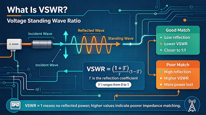
Voltage Standing Wave Ratio — universally abbreviated VSWR and sometimes pronounced "vizwer" — is one of the most frequently quoted figures of merit in RF and microwave engineering. It quantifies how much of a forward-traveling signal is reflected back toward the source due to impedance mismatch at a load, an antenna, a filter, or any other RF junction.
The name comes from the physical phenomenon it describes. When a forward wave on a transmission line encounters a mismatch, part of its energy reflects and travels backward. Forward and reflected waves at the same frequency and on the same line interfere, producing a stationary pattern of voltage maxima and minima along the line — a standing wave. The ratio of the maximum voltage to the minimum voltage at these points is, by definition, the VSWR.
VSWR is always greater than or equal to 1.0. A value of 1.0 means no reflection at all (a perfect match). A value tending toward infinity means total reflection, which happens at an open circuit, a short circuit, or a purely reactive mismatch. Real-world RF systems almost never see VSWR = 1.0; a well-designed system targets VSWR below 1.5:1 across its operating band.
VSWR is derived directly from the complex reflection coefficient Γ (gamma), which is the ratio of the reflected wave to the incident wave at the load. The relationship is:
VSWR = (1 + |Γ|) / (1 - |Γ|)
Γ itself is a complex number with magnitude between 0 and 1. When |Γ| = 0 (perfect match, no reflection), VSWR = 1.0. When |Γ| = 1 (total reflection), the denominator approaches zero and VSWR approaches infinity. The reflection coefficient at the load is itself computed from the load impedance ZL and the line's characteristic impedance Z₀:
Γ = (ZL − Z₀) / (ZL + Z₀)
For a 50 Ω system with a 75 Ω load (a common mismatch), Γ = (75 − 50)/(75 + 50) = 0.2, and VSWR = (1 + 0.2)/(1 − 0.2) = 1.5:1.
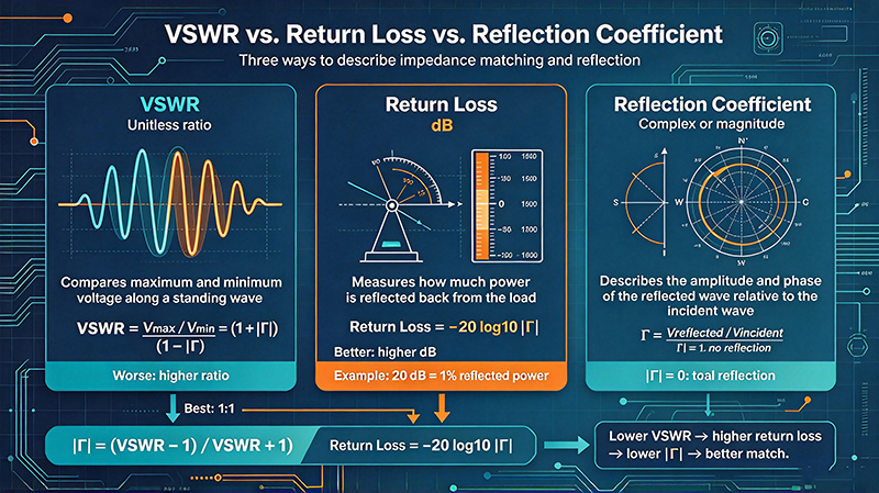
VSWR, return loss, and reflection coefficient magnitude all describe the same underlying mismatch — they are simply three different units or scales. Return loss RL is the most convenient in logarithmic work because it is additive when multiple mismatches occur in series:
RL (dB) = -20·log10(|Γ|) = -20·log10((VSWR-1)/(VSWR+1))
Higher return loss means a better match. An RL of 20 dB corresponds to VSWR = 1.22:1; an RL of 30 dB corresponds to VSWR ≈ 1.07:1; an RL of 10 dB corresponds to VSWR = 1.92:1.
| VSWR | Return Loss (dB) | Reflected Power (%) | Match Quality |
|---|---|---|---|
| 1.0 | ∞ | 0 | Perfect (theoretical) |
| 1.05 | 32.3 | 0.06 | Excellent — lab-grade components |
| 1.10 | 26.4 | 0.23 | Very good — production antennas |
| 1.20 | 20.8 | 0.92 | Good — most consumer RF products |
| 1.30 | 17.7 | 1.7 | Acceptable — many cost-sensitive systems |
| 1.50 | 13.9 | 3.5 | Acceptable — minimum for high-power TX |
| 2.00 | 9.5 | 11.1 | Poor — significant signal loss |
| 3.00 | 5.7 | 25.0 | Bad — system redesign recommended |
A high VSWR is more than a number — it has direct, measurable consequences. First, reflected power reduces the power delivered to the load. A 1.5:1 VSWR reflects about 4% of the incident power, so a 100 W transmitter delivers only 96 W to the antenna. Second, the reflected wave travels back to the source, where it can cause heating in power transistors or instability in oscillators. Third, the standing-wave pattern along the line increases peak voltages beyond the forward-only value, which can drive line insulation or connectors into breakdown.
In receivers, a high VSWR at the antenna feed degrades noise figure by presenting a non-50 Ω source impedance to the LNA. A 2:1 VSWR can add 0.5 dB or more to system NF, a critical penalty for weak-signal applications. In test systems, poor VSWR at any reference plane makes calibration meaningless.
Different applications tolerate different VSWR values. As a rule of thumb:
• Cellular and Wi-Fi consumer products: VSWR ≤ 2.0:1 across band (cost-driven design) • Professional wireless base stations: VSWR ≤ 1.5:1 across band • Radar and EW systems: VSWR ≤ 1.3:1 across band (sensitivity-driven) • Satellite ground terminals: VSWR ≤ 1.2:1 across band (link budget critical) • Test and measurement reference planes: VSWR ≤ 1.05:1 (calibration accuracy dependent)
For high-power transmitters (>100 W), VSWR should always be below 1.5:1 to keep reflected power within the transmitter's protection circuit threshold. If VSWR is higher, the transmitter's VSWR foldback circuit will reduce output power, and persistent mismatch can permanently damage the power amplifier.
VSWR is measured with a vector network analyzer (VNA), which provides the most accurate reflection-coefficient data including phase. The VNA is calibrated at the reference plane using a calibration kit (SOLT for coaxial, TRL for microstrip or waveguide) before measuring the device under test. The VNA directly displays S11 as magnitude, phase, or on a Smith chart; VSWR is computed and displayed automatically.
For quick field checks without a VNA, an SWR meter or antenna analyzer can be used. These are narrowband reflectometers that measure the ratio of forward to reflected power at a single frequency or a narrow sweep. They are less accurate than a VNA but are inexpensive, portable, and good enough for antenna tuning and field troubleshooting.
Reducing VSWR comes down to improving the match between the source, the transmission line, and the load. The most powerful technique is a matching network — an L-network, a single-stub tuner, a double-stub tuner, or a multi-section transformer — designed to transform the load impedance to the line's Z₀. For an antenna, this might mean trimming the radiating element's length, adding a capacitive hat, or placing a matching network at the feed point.
Other causes of high VSWR are connector problems: loose coupling nuts, worn contacts, contamination, or transitions between different cable types. Always use calibrated, torque-wrenched connectors and high-quality cable assemblies.
Q: Is VSWR the same as SWR? A: Yes — VSWR (voltage) and ISWR (current) are mathematically identical for a lossless line, and the term SWR is commonly used to mean either. In practice, "VSWR" is the dominant convention.
Q: What is the relationship between VSWR and S11? A: VSWR = (1 + |S11|)/(1 − |S11|). VSWR 1.5:1 corresponds to |S11| = 0.2 (−14 dB return loss). VSWR 2.0:1 corresponds to |S11| = 0.333 (−9.5 dB).
Q: Can VSWR be less than 1.0? A: No. VSWR is bounded below by 1.0, which corresponds to a perfect match. Any mismatch pushes VSWR above 1.0.
Q: Does VSWR change with frequency? A: Almost always yes. A wideband antenna may have VSWR < 1.5 across its design band but VSWR > 3.0 outside it. Always specify the frequency band when quoting a VSWR number.
Antenna installers used to use SWR meters that gave a single number across a band, then walk around the antenna adjusting elements until the meter read 1.5 or better. Modern antenna analyzers like the RigExpert AA-55, the MFJ-269, or the Comet CAA-500 show a real VSWR sweep across the entire band in seconds. The difference is dramatic — you can identify a 2.4 GHz Wi-Fi antenna's exact resonance within 1 MHz and tune it accordingly.
The number one cause of high VSWR in the field is connector installation. Crimp connectors are the worst offender: a slightly undersized crimp reduces the cable's effective diameter, changing its characteristic impedance and creating a mismatch. Soldered connectors are better but require skill to avoid cold joints. Pre-terminated cable assemblies from reputable manufacturers (Times Microwave, Commscope, RFS) eliminate the field-installation variable and are strongly preferred for any permanent installation.
A cellular carrier was experiencing reduced throughput on a 3.5 GHz 5G base station antenna. Field measurements showed VSWR of 2.1:1 at the antenna feed, well above the 1.5:1 design target. Investigation revealed a kinked jumper cable between the radio and the antenna — a maintenance crew had stepped on it during a tower climb, slightly crushing the dielectric. Replacing the cable with a new pre-terminated assembly brought VSWR down to 1.2:1, improving throughput by 15% across the coverage area. The total cost of the fix was $80 in cable and 30 minutes of tower time.
VSWR is the most basic and most informative measurement in any RF system. When in doubt about the integrity of a cable, an antenna, or a connector, measure VSWR first. The answer is almost always simple — replace the suspect component, retorque the connector, and the problem disappears.
Across telecommunications, aerospace, defense, medical imaging, and automotive radar, the concepts covered in this guide show up in every RF design. From 5G base stations deploying massive MIMO antenna arrays with dozens of Wilkinson dividers per panel, to satellite payloads where every decibel of link budget determines the success of a multi-million-dollar mission, the principles remain the same: measure carefully, design with margin, and verify with the right instrument.
Medical applications add another wrinkle: MRI machines operate at the Larmor frequency of hydrogen (42.58 MHz/Tesla) and require extraordinarily low noise and high stability. Test systems for MRI receivers must minimize cable loss between the imaging coil and the low-noise preamplifier — often mounted directly on the coil housing — because every dB of loss degrades diagnostic image quality. The same matching, cabling, and LNA placement principles apply.
Automotive radar at 77 GHz is one of the fastest-growing RF domains. Each modern car may contain 5–10 mmWave radar units for adaptive cruise control, blind-spot detection, and automated emergency braking. These radar modules contain calibrated Wilkinson dividers, matched patch antennas, beam-steering phase shifters, and integrated FMCW synthesizers — all built on low-cost PCB substrates and tested in production at volumes exceeding 100 million per year. The principles taught in this guide are what make that volume manufacturing possible.
Beyond the basics covered above, several advanced topics deserve attention as your designs mature. Multi-physics simulation — coupling electromagnetic, mechanical, and thermal effects in a single simulation — is increasingly important at mmWave frequencies where small dimensional changes from thermal expansion can shift the operating frequency. Tools like ANSYS HFSS, CST Studio Suite, and Cadence Clarity now include multi-physics capabilities that integrate structural and thermal solvers with the RF simulator.
Machine learning is beginning to appear in RF design. Surrogate models trained on simulation data can predict S-parameters 1000× faster than running the full EM simulation, enabling design space exploration that was previously impossible. Tools like Google Brain's RF antenna design work and Cadence's Cerebrus are early examples of where the field is heading. For now, these tools augment rather than replace the engineer's judgment — they accelerate iteration but the final design still needs to be understood, verified, and signed off by an experienced engineer.
Every RF system must comply with applicable regulatory standards. In the United States, Part 15 of the FCC rules governs intentional radiators and unintentional emissions. The European Union's Radio Equipment Directive (RED) does similar work. Specific applications have additional standards: ETSI EN 301 893 for 5 GHz Wi-Fi, ETSI EN 302 500 for UWB, and many others. Military and aerospace applications have additional standards: MIL-STD-461 for EMI, MIL-STD-810 for environmental, and MIL-STD-1540 for product assurance.
Compliance testing is a discipline of its own. Compliance test labs use specialized instruments (spectrum analyzers with quasi-peak detectors, EMI receivers calibrated to CISPR standards) and follow specific procedures. The measurement uncertainty of compliance tests is typically ±3 to ±6 dB — much wider than production test measurements, but required for regulatory acceptance. Plan for compliance testing early in your design cycle; retrofitting a product to meet EMI requirements after the design is finalized is expensive and time-consuming.
RF engineering is a deep specialty with strong demand and excellent compensation. The barrier to entry is high: unlike software, you cannot iterate in seconds, and the cost of mistakes is paid in physical hardware. Yet for engineers who take the time to develop intuition, RF offers some of the most satisfying engineering work available — every component choice has a measurable effect, and every measurement reveals something about the physical world.
For those starting out, build a home lab. Even a modest setup with a cheap SDR (RTL-SDR, HackRF, or Airspy), a few antennas, and some cables will let you explore the RF spectrum in ways that no simulator can. Add a low-end spectrum analyzer (Rigexpert, TinySA) when you can afford it, and a used VNA from eBay when the budget allows. The hands-on experience with real signals, real cables, and real instruments is what builds intuition that no textbook can provide.
Stay current by reading industry publications (Microwave Journal, RF Globalnet, Microwaves & RF), attending conferences (IMS, EuMW, IEEE MTT-S), and joining professional communities (IEEE MTT-S, ACM SIGCOMM for networking RF). The field evolves rapidly — mmWave 5G, satellite internet, and automotive radar were niche markets 10 years ago and are now mainstream. The engineers who built those markets started by mastering exactly the fundamentals covered in this article.
High-tech Enterprise, Feifeng Talent
Chief Engineer Wang graduated with a master's degree in high-power microwave from the Institute of Electronics, University of Chinese Academy of Sciences.
View Full Profile