




























What Is IP3?
IP3, or Third-Order Intercept Point, is one of the most important specifications for evaluating linearity in RF and microwave components. Learn what IP3 means, how it is calculated, how IIP3 and OIP3 differ, and why IP3 matters when selecting amplifiers, mixers, RF switches, and other microwave components.
What Is IP3?
IP3 stands for Third-Order Intercept Point. It is a theoretical measurement used to characterize the linearity of an RF or microwave device, particularly when the device is exposed to multiple signals at the same time.
In an ideal linear RF system, the output signal would be a scaled version of the input signal. Real-world components, however, are not perfectly linear. When an RF amplifier, mixer, receiver, or other active component processes multiple signals, nonlinear behavior can generate unwanted signals called intermodulation products.
Third-order intermodulation products are especially important because they can fall very close to the desired signals and are therefore difficult to filter out. IP3 provides engineers with a convenient way to quantify how resistant a component is to these third-order distortion products.
Why Is IP3 Important in RF and Microwave Systems?
Modern RF systems often operate in environments containing many signals simultaneously. A receiver may need to detect a weak signal while strong signals are present in adjacent channels or frequency bands. If the front-end components are insufficiently linear, these strong signals can produce intermodulation products that interfere with the desired signal.
IP3 is therefore an important parameter when evaluating the performance of:
- RF and microwave amplifiers
- Low-noise amplifiers (LNAs)
- Power amplifiers
- Mixers and frequency converters
- RF microwave switches
- Coaxial switches
- Receivers and transceivers
- RF front-end modules
- Base-station equipment
- Satellite communication systems
- Radar systems
- Wireless communication infrastructure
A component with a high IP3 can tolerate stronger interfering signals before third-order distortion becomes a significant limitation.
How Does IP3 Work?
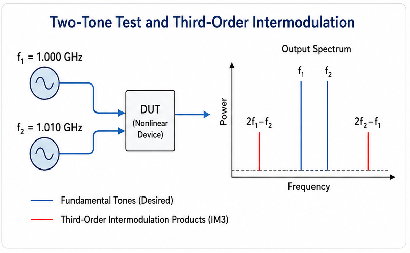
IP3 is commonly evaluated using a two-tone test. Two RF signals with closely spaced frequencies are applied to a nonlinear device.
Assume the two input frequencies are f₁ and f₂. Nonlinear behavior generates several new frequency components. The third-order intermodulation products of greatest concern are:
These products are located close to the original tones. For example, if the input signals are at 1.000 GHz and 1.010 GHz, third-order products can appear at 0.990 GHz and 1.020 GHz.
Because these frequencies can be close to the desired operating channels, third-order distortion can be particularly problematic in high-density RF environments.
What Is the Third-Order Intercept Point?
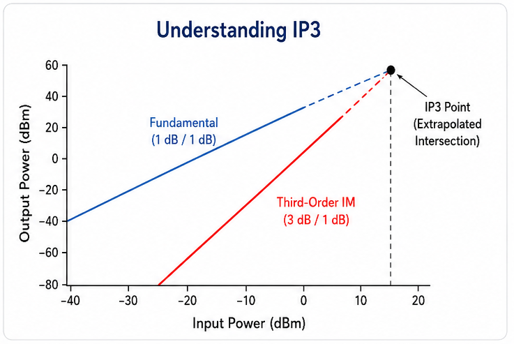
The third-order intercept point is obtained by extrapolating the fundamental output power and third-order intermodulation output power lines until they theoretically intersect.
For a two-tone test, the fundamental output power increases approximately 1 dB for every 1 dB increase in input power. The third-order intermodulation product increases approximately 3 dB for every 1 dB increase in input power.
If these two trends are extended mathematically, they eventually intersect at a point known as the third-order intercept point.
IIP3 vs. OIP3
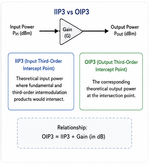
IP3 is commonly specified in two forms: IIP3 and OIP3.
IIP3
IIP3 means Input Third-Order Intercept Point. It represents the theoretical input power at which the extrapolated fundamental and third-order intermodulation products would intersect.
OIP3
OIP3 means Output Third-Order Intercept Point. It represents the corresponding theoretical output power at the third-order intercept point.
Relationship
For a device with small-signal gain G, the relationship is approximately OIP3 = IIP3 + G when all values are expressed in dBm and gain is expressed in dB.
For example, if an amplifier has an IIP3 of +10 dBm and a gain of 20 dB, its approximate OIP3 is +30 dBm.
How Is IP3 Measured?
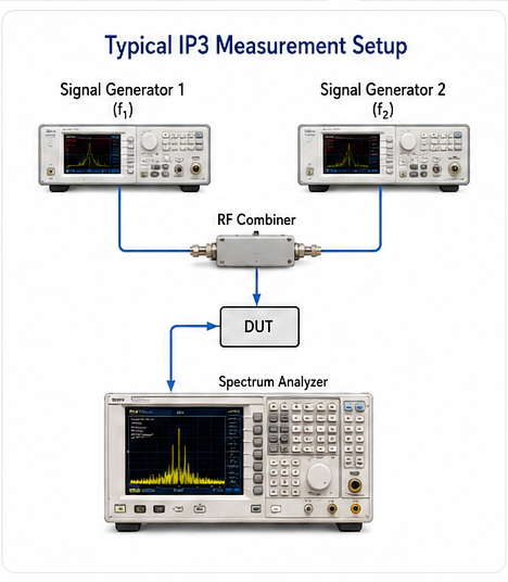
A common method for measuring IP3 is the two-tone test. The basic measurement setup typically includes two RF signal generators, a combiner, the device under test, and a spectrum analyzer or suitable RF measurement receiver.
Typical IP3 Measurement Procedure
- Generate two RF tones at closely spaced frequencies.
- Combine the two signals using an appropriate RF combiner.
- Apply the combined signal to the device under test.
- Measure the fundamental output tones.
- Measure the third-order intermodulation products.
- Increase the input level over an appropriate range.
- Determine the slopes of the fundamental and third-order products.
- Extrapolate the two lines to calculate IP3.
Accurate measurements require careful attention to signal-generator phase noise, harmonics, impedance matching, cable losses, connector quality, analyzer dynamic range, and the linearity of the measurement equipment itself.
IP3 Calculation
A convenient method for calculating OIP3 from a two-tone measurement uses the fundamental output power and the third-order intermodulation product level.
Here, POUT is the output power of one fundamental tone in dBm, and Δ is the difference in dB between the fundamental tone and the corresponding third-order intermodulation product.
For example, suppose the fundamental output level is +5 dBm and the third-order product is measured at −45 dBm. The difference is 50 dB.
If the device has 15 dB of gain, the corresponding IIP3 would be approximately:
IP3 and RF Linearity
Linearity describes how accurately an RF component processes signals without generating unwanted distortion. IP3 is one of the most widely used metrics for evaluating this behavior.
| Parameter | Meaning | Higher Value Generally Indicates |
|---|---|---|
| IIP3 | Input third-order intercept point | Better input-referred linearity |
| OIP3 | Output third-order intercept point | Better output-referred linearity |
| IM3 | Third-order intermodulation product | Lower level means less distortion |
| P1dB | 1 dB compression point | Greater large-signal capability |
Although IP3 and P1dB are both related to RF linearity, they describe different aspects of device behavior and should not be treated as interchangeable specifications.
IP3 vs. P1dB
The 1 dB compression point (P1dB) indicates when the gain of an RF device has compressed by approximately 1 dB from its small-signal behavior. It is a practical indicator of large-signal handling capability.
IP3, in contrast, is derived from the relationship between the fundamental and third-order distortion products. It is primarily used to evaluate third-order linearity.
In RF system design, engineers often consider both parameters. A component may have a good P1dB but still generate unacceptable intermodulation products under certain multi-tone conditions.
IP3 vs. Noise Figure
IP3 and noise figure are two critical parameters in RF receiver design, but they measure different performance characteristics.
- Noise figure: Describes how much a device degrades the signal-to-noise ratio.
- IP3: Describes resistance to third-order nonlinear distortion.
Low-noise amplifiers often require a careful balance between noise figure, gain, IP3, power consumption, and operating frequency. Optimizing one parameter does not necessarily optimize the others.
Why a High IP3 Matters for RF Microwave Switches
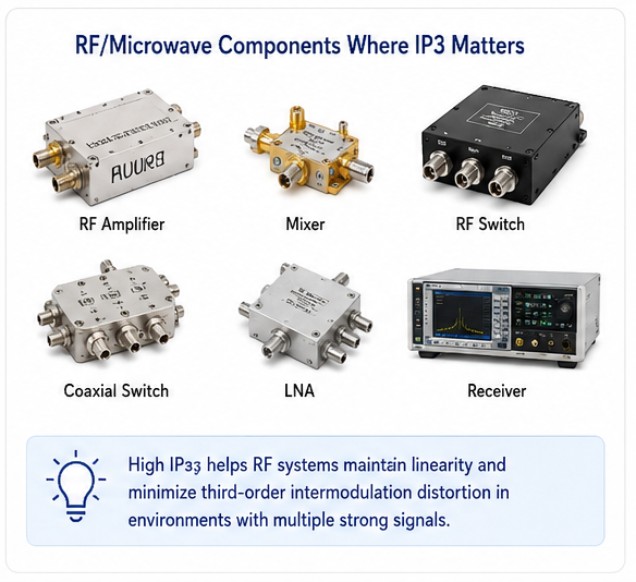
RF microwave switches are frequently used to route signals between multiple test paths, antennas, filters, amplifiers, and measurement instruments. In multi-channel systems, switch linearity can affect overall signal integrity.
A high-IP3 RF switch produces lower third-order intermodulation distortion when multiple signals pass through the switch simultaneously. This can be particularly important in:
- 5G and wireless communication testing
- RF automated test equipment
- Satellite communication test systems
- Radar test equipment
- Multi-channel receiver systems
- Signal routing and switching matrices
- RF production test systems
When selecting an RF coaxial switch, IP3 should be evaluated together with insertion loss, isolation, VSWR, power handling, switching speed, frequency range, and switching lifetime.
What Factors Affect IP3?
1. Device Architecture
The internal topology and semiconductor technology of an RF component strongly influence its linearity. Different amplifier, mixer, switch, and detector architectures can have substantially different IP3 characteristics.
2. Input Power
Intermodulation distortion generally becomes more significant as input power increases. IP3 measurements must therefore be performed within a suitable operating region.
3. Frequency
RF linearity can vary significantly with frequency. A component's IP3 specification should always be considered at the actual operating frequency or frequency range of the application.
4. Bias Conditions
For active RF devices, supply voltage and bias current can affect gain, compression, and nonlinear behavior. IP3 may therefore change with operating conditions.
5. Temperature
Semiconductor characteristics can change with temperature, potentially affecting gain and linearity. For demanding applications, IP3 should be evaluated across the required temperature range.
6. Matching and System Layout
Impedance mismatch, PCB layout, connectors, cables, and other components can influence the measured system-level linearity. Proper 50-ohm RF design is essential for reliable measurements.
How to Choose an RF Component Based on IP3
Choosing an RF component solely according to its highest IP3 specification is not always the best engineering approach. The required IP3 depends on the signal environment and system architecture.
- Determine the maximum expected input signal level.
- Identify the strongest interfering signals.
- Determine the acceptable third-order distortion level.
- Compare IIP3 or OIP3 specifications under the actual operating conditions.
- Check the frequency range and bandwidth.
- Evaluate noise figure and gain when applicable.
- Check P1dB and maximum input power for large-signal applications.
- Consider insertion loss, isolation, VSWR, and power handling for RF switches.
Common Applications of IP3
5G Communications
IP3 helps evaluate receiver and RF front-end linearity in environments containing multiple strong signals.
Radar Systems
High linearity can reduce unwanted intermodulation products that may interfere with sensitive radar signal processing.
Satellite Communications
IP3 is important when multiple carriers share RF hardware and nonlinear distortion must be controlled.
RF Test Equipment
Signal analyzers, generators, switches, amplifiers, and routing systems often require high linearity for accurate testing.
Wireless Base Stations
High-IP3 components help manage the effects of multiple carriers and strong adjacent-channel signals.
Receiver Front Ends
IP3 helps engineers assess whether an RF front end can maintain signal integrity in the presence of strong interferers.
Frequently Asked Questions About IP3
What does IP3 stand for?
IP3 stands for Third-Order Intercept Point. It is a theoretical parameter used to characterize the third-order linearity of an RF or microwave device.
Is a higher IP3 better?
Generally, yes. A higher IP3 usually indicates better resistance to third-order intermodulation distortion. However, IP3 should be evaluated together with other specifications such as noise figure, gain, P1dB, insertion loss, and power handling.
What is the difference between IIP3 and OIP3?
IIP3 is the input-referred third-order intercept point, while OIP3 is the output-referred third-order intercept point. Approximately, OIP3 = IIP3 + gain.
What are third-order intermodulation products?
For two input tones at f₁ and f₂, important third-order products occur at 2f₁ − f₂ and 2f₂ − f₁. Because these products can be close to the desired signals, they can be difficult to filter.
Is IP3 the same as P1dB?
No. IP3 characterizes third-order intermodulation behavior, while P1dB identifies the approximate point where the fundamental gain has compressed by 1 dB. Both are useful RF linearity specifications.
What unit is IP3 measured in?
IP3 is commonly expressed in dBm because it represents a theoretical power level. IIP3 and OIP3 can therefore be directly compared with other power-related RF specifications when the measurement conditions are understood.
Conclusion
IP3 is a fundamental RF specification for evaluating third-order linearity. It helps engineers understand how an RF or microwave component behaves when multiple signals are present and how susceptible the system may be to third-order intermodulation distortion.
The two most common forms are IIP3 and OIP3. IIP3 refers to the input-referred intercept point, while OIP3 refers to the output-referred intercept point. A higher IP3 generally indicates better linearity and improved tolerance to strong interfering signals.
When selecting RF amplifiers, mixers, microwave switches, coaxial switches, or other RF components, IP3 should not be considered in isolation. Engineers should evaluate it alongside noise figure, gain, P1dB, insertion loss, isolation, VSWR, frequency range, and power handling to achieve the required system performance.
About the Author — MeiXun Team
Chief Engineer Wang
High-tech Enterprise, Feifeng Talent
Chief Engineer Wang graduated with a master's degree in high-power microwave from the Institute of Electronics, University of Chinese Academy of Sciences.
View Full Profile- RF Switch Circuit Diagram
- RF Switch
- Ohm's Law
- dBm to Watt
- mW to dBm
- Wavelength to Frequency
- RF Connector
- SMA Connector
- RF Switch Module
- RF Coupler
- RF PIN Switch
- Microwave Coaxial Switch
- PIN Switch
- Coaxial RF Switch
- Waveguide Switch
- Microwave Switch
- Low Noise Amplifier
- PIN Diode Switch
- Coaxial Switch
- RF Microwave Switch
- SPST Switch