




























RF Switch Troubleshooting: Common Failures and Solutions
RF switches are mission-critical components in test & measurement systems, wireless base stations, radar, satellite payloads, and aerospace avionics. When a switch fails or drifts out of spec, the entire signal chain can degrade—causing dropped calls, failed production tests, or compromised radar tracks. This guide walks you through the most common RF switch failures, how to diagnose them, and proven solutions to restore performance quickly.
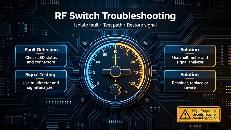
Table of Contents
1. How RF Switches Work
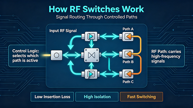
An RF switch routes high-frequency signals between multiple ports. The two dominant technologies are:
- Electromechanical (EM) switches – use magnetic latching relays or solenoids to physically move a contact. Typical life: 5–10 million cycles. Excellent isolation (>80 dB) and low insertion loss up to 40 GHz.
- Solid-state switches (PIN diode or GaAs FET) – switch electronically in microseconds. Lower isolation (40–60 dB), higher insertion loss, but virtually unlimited switching cycles.
Understanding the technology helps you predict which failures are likely.
2. Symptoms of a Failing RF Switch
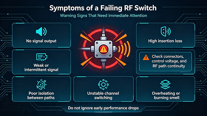
Watch for these telltale signs in your system:
- Sudden or gradual rise in insertion loss
- Drop in isolation between ports
- Increased VSWR / return loss
- Intermittent or stuck channels (no switching)
- Slow or inconsistent switching speed
- Noise, microphonics, or unstable readings
- Visible arc damage or burn marks on connectors
3. The 7 Most Common RF Switch Failures
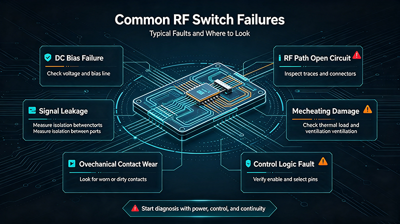
3.1 High Insertion Loss
Cause: Contaminated or oxidized internal contacts, worn plating, loose connector mating, or damaged center conductors.
Where it occurs: Most often at SMA, N-Type, or TNC interfaces.
3.2 Poor Isolation
Cause: Failed relay coil (in EM switches), cracked PCB traces, or PIN diode leakage in solid-state switches.
Symptom: Signal bleeds between OFF ports—measurable on a VNA with the unused ports terminated.
3.3 High VSWR / Return Loss
Cause: Mechanical deformation of the contact, connector over-torque, or impedance mismatch from internal damage.
3.4 Stuck or Intermittent Channels
Cause: Driver circuit failure, insufficient actuation voltage/current, cold solder joints, or mechanical jam inside a latching relay.
3.5 Slow Switching Speed
Cause: Aging driver transistors, increased coil resistance (in EM switches), or thermal drift in solid-state switches.
3.6 Contact Sticking / Welding
Cause: Hot-switching (switching under high RF power) creates micro-arcing that welds contacts together.
3.7 Physical Connector Damage
Cause: Repeated mating cycles, improper torque (over- or under-tightening), or axial/radial stress on cables.
| Failure Mode | Primary Cause | Quick Indicator |
|---|---|---|
| High insertion loss | Oxidation, worn plating | S-parameter S21 degraded |
| Poor isolation | Coil failure, PIN leakage | S31 / S41 leakage rises |
| High VSWR | Mechanical deformation | Return loss < datasheet |
| Stuck channel | Driver / actuation issue | No continuity change |
| Slow speed | Aging driver | Rise/fall time exceeded |
| Welded contact | Hot-switching | Permanent short |
| Connector damage | Mechanical wear | Visual inspection |
4. Step-by-Step Diagnostic Procedure
- Visual Inspection: Check connectors for bent pins, discoloration, or debris.
- Verify Drive Signal: Use an oscilloscope to confirm the control voltage/current meets spec (e.g., 24 V / 100 mA for a latching relay).
- Measure S-Parameters: Use a calibrated vector network analyzer (VNA) to test S21, S11, and isolation (S31, S41).
- Terminate Unused Ports: Always terminate with 50 Ω loads to avoid measurement errors.
- Cycle Test: Command the switch to toggle thousands of times while monitoring parameters for drift.
- Compare to Baseline: Reference the manufacturer's datasheet and your own golden-unit data.
- Isolate the Subsystem: Bypass the switch to confirm downstream components are healthy.
5. Proven Solutions & Repair Strategies
5.1 Clean the Connectors
Use a lint-free swab and isopropyl alcohol (IPA, >99%) to clean mating surfaces. For EM switches with internal contacts, follow the manufacturer's purge procedure—never use abrasive cleaners.
5.2 Replace Damaged Cables and Connectors
If VSWR is high only on one channel, suspect the cable assembly, not the switch. Replace with a calibrated test cable.
5.3 Repair or Replace the Driver Board
Most "stuck channel" issues are resolved by replacing a failed transistor or MOSFET on the driver PCB. Check solder joints under magnification first.
5.4 Recalibrate or Re-terminate
Poor VSWR often traces to improper connector torque. Use a calibrated torque wrench (8 in-lbs for SMA, 12 in-lbs for Type-N).
5.5 Replace the Switch Module
When insertion loss or isolation cannot be restored to spec, swap the entire switch. EM switches can sometimes be returned to the factory for relay replacement.
5.6 Upgrade the Switch Type
If hot-switching is unavoidable, migrate from electromechanical to solid-state PIN or GaAs switches rated for the application.
5.7 Add Attenuation or Limiting
Install a limiter upstream to protect the switch from transients and ESD events that accelerate wear.
6. Preventive Maintenance Best Practices
- Cap all connectors when not in use to prevent contamination.
- Use calibrated torque wrenches on every mating.
- Avoid hot-switching—sequence the system so RF power is off before toggling.
- Log S-parameter trends annually to catch drift early.
- Operate within temperature, humidity, and vibration limits specified by the manufacturer.
- Schedule periodic factory recalibration every 12–24 months for mission-critical systems.
7. Frequently Asked Questions
Q1: How long do RF switches typically last?
Electromechanical switches: 5–10 million cycles. Solid-state switches: hundreds of millions, but degrade in isolation over time when exposed to high power.
Q3: Can I repair an RF switch myself?
You can clean connectors and replace cables, but internal relay or PIN-diode repairs require specialized equipment. Send to the OEM or authorized service center.
Q3: Why does my switch show good S21 but high VSWR?
VSWR reflects impedance mismatch—often a damaged connector or loose center pin—while insertion loss (S21) can still be acceptable.
Q4: How do I know if I'm hot-switching?
If RF power is present when the switch toggles, you are hot-switching. Check timing with an oscilloscope on the RF detector and switch control line.
Q5: Are solid-state switches better than electromechanical?
For speed and lifetime, yes. For isolation and low loss up to 40 GHz, electromechanical still wins. Choose based on your priority.
8. Conclusion
RF switch failures almost always fall into one of seven categories: insertion loss, isolation, VSWR, stuck channels, slow speed, contact welding, or connector damage. With a systematic approach—visual inspection, drive verification, VNA measurement, and cycle testing—you can pinpoint the root cause quickly. Pair these diagnostics with preventive maintenance (proper torque, no hot-switching, periodic recalibration) and your RF switches will deliver years of reliable service.
For mission-critical applications, partner with a supplier who offers traceable calibration, rapid RMA turnaround, and on-site application engineering support.
About the Author — MeiXun Team
Chief Engineer Wang
High-tech Enterprise, Feifeng Talent
Chief Engineer Wang graduated with a master's degree in high-power microwave from the Institute of Electronics, University of Chinese Academy of Sciences.
View Full Profile- RF Switch Circuit Diagram
- RF Switch
- Ohm's Law
- dBm to Watt
- mW to dBm
- Wavelength to Frequency
- RF Connector
- SMA Connector
- RF Switch Module
- RF Coupler
- RF PIN Switch
- Microwave Coaxial Switch
- PIN Switch
- Coaxial RF Switch
- Waveguide Switch
- Microwave Switch
- Low Noise Amplifier
- PIN Diode Switch
- Coaxial Switch
- RF Microwave Switch
- SPST Switch