




























RF Microwave Switches: Types, Applications, and How to Choose the Right One
RF microwave switches are essential components used to control the routing of high-frequency signals between multiple RF paths. They enable engineers to connect, disconnect, or redirect microwave signals without manually changing cables or physically reconfiguring a system. From radar and satellite communications to 5G networks, automated test equipment, and aerospace systems, RF switches play a critical role in modern high-frequency electronics.
Choosing the right RF microwave switch requires more than simply matching the operating frequency. Engineers must consider insertion loss, isolation, switching speed, power handling, VSWR, impedance, reliability, control method, and the specific requirements of the application. This guide explains the main types of RF microwave switches and provides practical recommendations for selecting the best solution.
What Is an RF Microwave Switch?
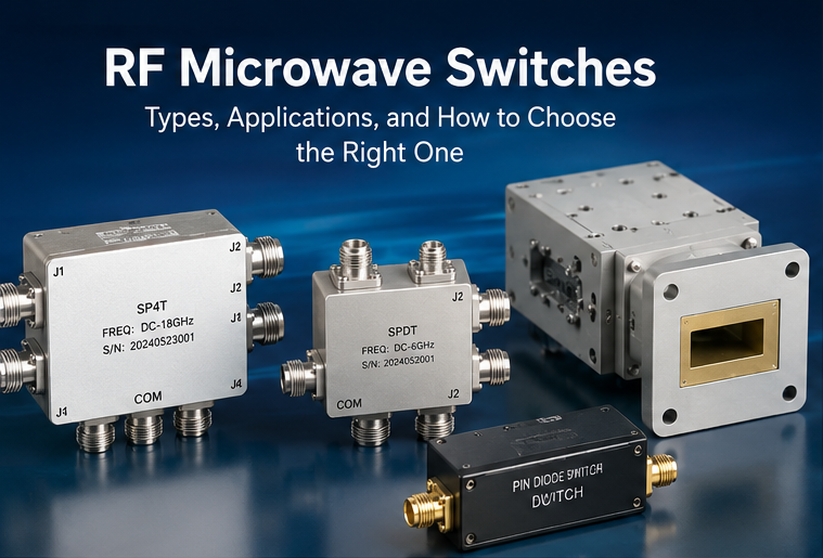
An RF microwave switch is an electronic or electromechanical device that controls the path of radio frequency and microwave signals within a circuit or system. Depending on its configuration, an RF switch can connect one input to one of several outputs, route multiple signals, or isolate unused signal paths.
RF microwave switches are commonly designed for frequencies ranging from hundreds of megahertz to tens of gigahertz and beyond. They are available in various technologies, including coaxial switches, waveguide switches, PIN diode switches, solid-state switches, and electromechanical RF switches.
The primary purpose of an RF microwave switch is to provide reliable signal routing while maintaining excellent RF performance. An ideal switch would introduce zero insertion loss, provide infinite isolation, operate instantly, and handle unlimited RF power. In practice, engineers must balance these parameters according to the system's requirements.
How Do RF Microwave Switches Work?
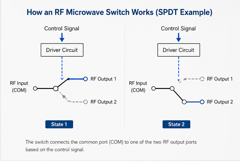
The basic operating principle of an RF microwave switch is straightforward: the device changes the electrical connection between different RF signal paths based on a control signal or mechanical actuation.
In a typical single-pole, double-throw configuration, one common RF port can be connected to either of two output ports. When the switch receives a control command, it changes the active signal path and isolates the unused path.
The switching mechanism depends on the technology used. Electromechanical switches use physical components to establish or interrupt the RF connection. Solid-state switches use semiconductor devices such as PIN diodes or field-effect transistors to control signal transmission electronically.
The choice of switching technology has a direct impact on switching speed, RF power handling, insertion loss, isolation, lifetime, and reliability.
Major Types of RF Microwave Switches
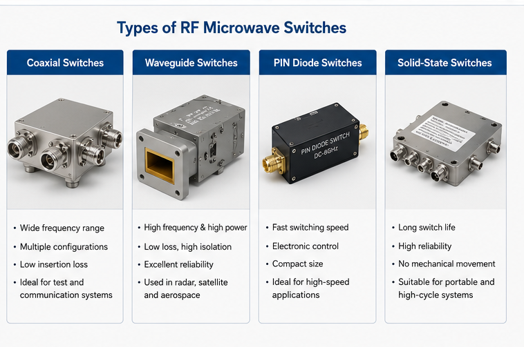
RF microwave switches can be categorized according to their switching technology, mechanical structure, and circuit configuration. The most common types include coaxial switches, waveguide switches, PIN diode switches, and solid-state RF switches.
Coaxial RF Switches
Coaxial switches use coaxial transmission lines and are widely used for RF signal routing, automated test systems, communication equipment, and measurement applications. They offer broad frequency coverage and are available in configurations such as SPDT, SP3T, SP4T, and SP6T.
Waveguide Switches
Waveguide switches are designed for high-frequency microwave applications where low insertion loss, high power handling, and excellent isolation are required. They are commonly found in radar, satellite communication, aerospace, and defense systems.
PIN Diode Switches
PIN diode switches use semiconductor PIN diodes to control RF signal transmission. They provide fast switching speeds and are suitable for applications requiring rapid electronic signal routing.
Solid-State RF Switches
Solid-state RF switches use semiconductor technologies to provide fast switching without mechanical movement. They are suitable for compact systems, high switching cycle requirements, and applications where fast response is essential.
RF Microwave Switch Configurations
In addition to switching technology, RF switches are classified by their port configuration. Understanding these configurations helps engineers select the appropriate device for a particular signal-routing architecture.
SPST RF Switch
A single-pole, single-throw (SPST) switch has one input and one output. It functions similarly to an RF on/off switch and is commonly used to connect or disconnect a single signal path.
SPDT RF Switch
A single-pole, double-throw (SPDT) switch has one common port and two selectable ports. It allows one RF signal to be routed between two different paths and is one of the most widely used RF switch configurations.
SP3T and SP4T RF Switches
SP3T and SP4T switches allow a single input to be routed to three or four output paths. These configurations are useful in test systems, communication equipment, antenna switching networks, and RF measurement platforms.
Multi-Throw and Multi-Port RF Switches
More complex systems may require switches with multiple inputs and outputs. Multi-port RF switches provide flexible signal routing and can significantly simplify system architecture by replacing multiple individual switches.
Key RF Microwave Switch Specifications
Selecting an RF microwave switch requires careful evaluation of its electrical and mechanical specifications. The following parameters are particularly important.
| Specification | What It Means | Why It Matters |
|---|---|---|
| Frequency Range | The range of RF frequencies supported by the switch. | Ensures the switch can operate correctly across the required frequency band. |
| Insertion Loss | The amount of signal power lost when the switch is in the ON state. | Lower insertion loss improves overall system efficiency and signal integrity. |
| Isolation | The level of signal suppression between isolated ports. | High isolation helps prevent unwanted signal leakage and interference. |
| VSWR | Voltage Standing Wave Ratio, indicating impedance matching quality. | Lower VSWR generally means better impedance matching and reduced signal reflection. |
| Switching Speed | The time required to change from one RF state to another. | Critical for radar, communications, and high-speed automated test applications. |
| Power Handling | The maximum RF power the switch can safely handle. | Important for transmitters, radar systems, and high-power microwave applications. |
| Impedance | The characteristic impedance of the RF transmission path. | Most RF systems use 50-ohm impedance for compatibility and signal integrity. |
| Switching Life | The expected number of switching cycles for the device. | Important for systems requiring frequent switching and long-term reliability. |
Applications of RF Microwave Switches
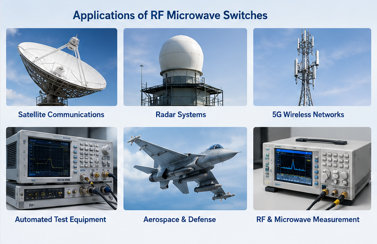
RF microwave switches are used in a wide variety of industries because they provide flexible and reliable control of high-frequency signals.
1. Radar Systems
Radar systems use RF switches to route signals between transmitters, receivers, antennas, and signal-processing circuits. High isolation and power handling are particularly important in radar applications because the switch may need to protect sensitive receiver components from high-power transmit signals.
2. Wireless and 5G Communications
RF switches are used in wireless infrastructure, 5G systems, antenna networks, and radio equipment to control signal paths and support multiple operating modes. Low insertion loss and high isolation help maintain signal quality and system efficiency.
3. Satellite Communications
Satellite communication systems require highly reliable microwave components for signal routing and redundancy. Waveguide switches and high-performance coaxial switches are often used in ground stations and satellite RF subsystems.
4. Automated Test Equipment
Automated test equipment relies heavily on RF switches to connect measurement instruments to multiple devices under test. Switching networks can automate RF measurements while reducing the need for manual cable connections.
5. Aerospace and Defense
Aerospace and defense systems often require high-reliability RF switching components for radar, electronic warfare, communication, and navigation systems. These applications may require exceptional environmental performance, high isolation, and robust mechanical construction.
6. RF and Microwave Measurement Systems
RF microwave switches are widely used in network analyzers, signal generators, spectrum measurement systems, and other laboratory equipment. They allow engineers to automatically select different signal paths and measurement configurations.
How to Choose the Right RF Microwave Switch
The best RF microwave switch depends on the electrical, mechanical, environmental, and operational requirements of the application. The following selection process can help engineers identify the right solution.
Step 1: Determine the Operating Frequency
Start by identifying the minimum and maximum operating frequencies of the system. The RF switch should provide adequate performance across the entire required frequency range. Selecting a switch with sufficient frequency margin can also improve design flexibility.
Step 2: Check Insertion Loss Requirements
If the application has strict signal budget requirements, select a switch with low insertion loss. Excessive insertion loss can reduce received signal strength and negatively affect the overall performance of the RF system.
Step 3: Evaluate Isolation
High isolation is critical when unwanted signals between ports could cause interference, measurement errors, or receiver damage. Radar, test equipment, and multi-channel communication systems often require excellent port-to-port isolation.
Step 4: Consider RF Power Handling
Determine the maximum continuous-wave and peak RF power that the switch will encounter. High-power systems may require specialized coaxial or waveguide switches designed to withstand demanding RF conditions.
Step 5: Select the Appropriate Switching Technology
Choose between electromechanical, PIN diode, and other solid-state technologies based on switching speed, lifetime, insertion loss, isolation, and power requirements.
- Choose electromechanical RF switches when high isolation and low insertion loss are priorities.
- Choose PIN diode switches when fast electronic switching is required.
- Choose coaxial switches for flexible RF signal routing across broad frequency ranges.
- Choose waveguide switches for demanding high-frequency and high-power microwave applications.
- Choose solid-state switches for high switching-cycle applications requiring compact designs.
Step 6: Consider Switching Speed
Switching speed is especially important for systems that need rapid signal path changes. Solid-state and PIN diode switches generally provide faster switching than traditional electromechanical designs.
Step 7: Evaluate Mechanical and Environmental Requirements
For aerospace, defense, outdoor communication, and industrial applications, consider temperature range, vibration, shock, humidity, altitude, connector type, mounting requirements, and expected operating lifetime.
Step 8: Verify Control Interface and Integration
Ensure that the switch control interface is compatible with the system. Depending on the design, RF switches may use TTL, parallel control, serial interfaces, or other customized control methods.
Quick Selection Checklist
- Confirm the required frequency range.
- Define the maximum RF power level.
- Set acceptable insertion loss limits.
- Determine the required isolation level.
- Check VSWR and impedance requirements.
- Define switching speed requirements.
- Select the appropriate number of ports.
- Consider switching cycle life and reliability.
- Verify connector and mounting options.
- Check environmental and operating conditions.
- Confirm control interface compatibility.
- Evaluate supplier quality, customization capability, and technical support.
RF Microwave Switches vs. Other RF Switching Technologies
Different RF switching technologies offer different advantages. There is no single solution that is ideal for every application.
| Technology | Main Advantages | Typical Applications |
|---|---|---|
| Electromechanical RF Switch | High isolation, low insertion loss, strong power handling | Test equipment, radar, communication systems |
| PIN Diode Switch | Fast switching, electronic control, high reliability | Radar, wireless communication, RF signal routing |
| Solid-State RF Switch | Fast operation, compact size, high switching cycle capability | Portable equipment, communication systems, instrumentation |
| Waveguide Switch | Low loss at microwave frequencies, high power capability | Radar, satellite, aerospace, defense |
Common Mistakes When Selecting an RF Microwave Switch
Selecting an RF switch based only on frequency is one of the most common mistakes in RF system design. A device may support the required frequency but still fail to meet the application's insertion loss, isolation, power, or reliability requirements.
Another common mistake is ignoring the difference between continuous-wave power and peak power. Pulsed radar systems, for example, may have very different power requirements from continuous-wave communication systems.
Engineers should also consider the entire RF signal chain. A switch with excellent performance may not deliver the expected system-level results if connectors, cables, filters, amplifiers, and other microwave components introduce significant losses or impedance mismatches.
Why RF Switch Quality Matters
The performance of an RF microwave switch can directly influence the overall performance of a high-frequency system. Poor insertion loss can reduce signal strength, insufficient isolation can create interference, and inadequate power handling can lead to component failure.
For this reason, professional RF microwave switch manufacturers typically evaluate electrical performance, mechanical reliability, environmental stability, and production consistency. Applications with demanding performance requirements may also require customized frequency ranges, connectors, control interfaces, mounting configurations, or environmental specifications.
Frequently Asked Questions About RF Microwave Switches
What is the main purpose of an RF microwave switch?
The main purpose of an RF microwave switch is to control and route high-frequency signals between different RF paths. It allows a system to select, connect, or isolate signal channels without manually changing the physical connections.
What is the difference between a coaxial switch and a waveguide switch?
Coaxial switches use coaxial transmission lines and are suitable for a broad range of RF applications. Waveguide switches use waveguide transmission structures and are generally preferred for high-frequency microwave systems requiring low loss and high power handling.
Are PIN diode switches faster than electromechanical RF switches?
In general, PIN diode switches provide faster electronic switching than electromechanical switches because they do not rely on physical mechanical movement. However, the best technology depends on the required isolation, insertion loss, power handling, and system architecture.
What is insertion loss in an RF switch?
Insertion loss is the amount of RF signal power lost when the switch is in its ON state. Lower insertion loss is generally desirable because it minimizes signal attenuation and helps preserve system performance.
Why is isolation important in RF microwave switches?
Isolation measures how effectively the switch prevents signals from passing between ports that should be disconnected. High isolation is important for reducing interference, protecting sensitive receivers, and maintaining signal integrity.
How do I choose an RF microwave switch manufacturer?
Consider the manufacturer's RF performance capabilities, product frequency range, customization options, quality control, testing procedures, manufacturing experience, delivery capability, and technical support. A reliable manufacturer should be able to provide detailed specifications and support the requirements of your application.
Conclusion
RF microwave switches are fundamental components in modern RF and microwave systems, providing reliable signal routing across applications ranging from radar and satellite communications to 5G networks, automated test equipment, aerospace, and defense.
The right RF microwave switch depends on a combination of factors, including frequency range, insertion loss, isolation, VSWR, power handling, switching speed, port configuration, reliability, and environmental requirements. Coaxial switches are highly versatile for many RF signal-routing applications, while waveguide switches are well suited to demanding microwave and high-power systems. PIN diode and solid-state switches are excellent choices when fast electronic switching is required.
By carefully evaluating the technical specifications and matching the switching technology to the application, engineers can achieve better RF performance, improved system reliability, and longer operating life. Working with an experienced microwave components manufacturer can also help ensure that the selected RF switch meets both standard and customized system requirements.
About the Author — MeiXun Team
Chief Engineer Wang
High-tech Enterprise, Feifeng Talent
Chief Engineer Wang graduated with a master's degree in high-power microwave from the Institute of Electronics, University of Chinese Academy of Sciences.
View Full Profile- RF Switch Circuit Diagram
- RF Switch
- Ohm's Law
- dBm to Watt
- mW to dBm
- Wavelength to Frequency
- RF Connector
- SMA Connector
- RF Switch Module
- RF Coupler
- RF PIN Switch
- Microwave Coaxial Switch
- PIN Switch
- Coaxial RF Switch
- Waveguide Switch
- Microwave Switch
- Low Noise Amplifier
- PIN Diode Switch
- Coaxial Switch
- RF Microwave Switch
- SPST Switch