


























DATE
June 9-11, 2026
LOCATION
Thomas M. Menino Convention & Exhibition Center
Boston, MA
May 26 ,26


5G communication testing, wireless terminal automated testing
Aerospace communication systems
Precision measurement equipment, radio frequency signal control of radar transmitters
Communication and navigation systems
Optical communication module-related testing
Interconnection of wireless communication base stations
Aerospace navigation systems operate under conditions that are significantly more demanding than typical commercial RF applications. Temperature extremes, vibration, shock, radiation, humidity, pressure changes, electromagnetic interference, and strict size and weight constraints can all affect RF performance. Selecting the right RF components for aerospace and harsh-environment navigation systems therefore requires more than comparing frequency range and insertion loss.
RF switches, coaxial connectors, filters, amplifiers, attenuators, power dividers, directional couplers, waveguide components, and other microwave components must maintain predictable electrical and mechanical performance throughout the intended mission profile. This guide explains the key selection criteria and design considerations for reliable aerospace RF navigation systems.
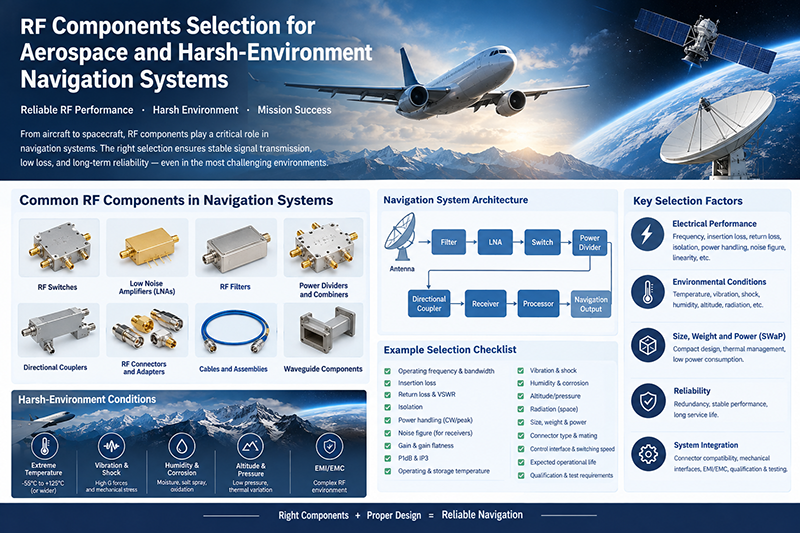
Navigation systems depend on precise RF signal transmission, reception, filtering, amplification, and switching. A small degradation in RF performance can reduce signal-to-noise ratio, increase measurement uncertainty, or compromise the availability of a navigation subsystem.
Aerospace applications can include aircraft navigation, satellite navigation payloads, inertial navigation augmentation, unmanned aerial vehicles, avionics communication systems, radar-assisted navigation, and spacecraft systems. Each application can impose different electrical, environmental, mechanical, and reliability requirements.
Key principle: An RF component should be selected based on the complete system environment rather than electrical specifications alone. Frequency range, power handling, environmental ratings, mechanical construction, reliability, and integration requirements should be evaluated together.
Aerospace navigation architectures commonly combine multiple RF components to route, condition, amplify, isolate, and measure high-frequency signals.
RF switches are used to select signal paths, redundant channels, antennas, test ports, and different operating modes. Depending on the architecture, designers may use SPDT, SP3T, SP4T, SP6T, SP8T, SP12T, or more complex switching configurations.
Important specifications include insertion loss, isolation, switching speed, return loss, power handling, frequency range, switching life, and control interface. For aerospace systems, mechanical robustness and repeatable performance across temperature are also important.
A low noise amplifier (LNA) is commonly positioned close to a sensitive receiver input where the signal level may be extremely low. Its primary functions are to provide gain while introducing as little additional noise as practical.
Important LNA parameters include noise figure, gain, gain flatness, input and output return loss, P1dB compression point, third-order intercept point, supply requirements, and operating temperature range.
RF filters remove unwanted frequencies and help protect sensitive receiver chains from interference. Depending on the application, designers may use low-pass, high-pass, band-pass, band-stop, cavity, ceramic, SAW, or waveguide filters.
For navigation systems operating near high-power transmitters or dense RF environments, filter rejection and out-of-band performance can be just as important as insertion loss.
Power dividers distribute an RF signal among multiple channels, while combiners perform the reverse function. These components can be used in antenna networks, redundant signal paths, phased-array architectures, test systems, and receiver distribution networks.
Designers should evaluate amplitude balance, phase balance, insertion loss, isolation, return loss, frequency range, and power handling.
Directional couplers provide controlled coupling between transmission paths and are frequently used for RF monitoring, power measurement, signal sampling, and feedback.
Coupling level, directivity, insertion loss, return loss, frequency bandwidth, and power rating should be matched to the measurement and control architecture.
RF connectors can become a critical source of system loss or mismatch if they are poorly selected or improperly integrated. Depending on the frequency and mechanical requirements, aerospace systems may use SMA, 2.92 mm, 2.4 mm, 1.85 mm, N-type, TNC, SMP, SMPM, or specialized RF interfaces.
Connector selection should consider frequency, impedance, mating cycles, vibration resistance, environmental sealing, cable compatibility, size, weight, and mechanical retention.
Electrical specifications define how an RF component interacts with the signal chain. Several parameters should be considered together rather than evaluated independently.
| Parameter | Why It Matters | Typical Design Concern |
|---|---|---|
| Frequency Range | Defines the usable RF operating band. | Ensure sufficient margin beyond the nominal operating frequency. |
| Insertion Loss | Determines how much signal power is lost through the component. | Critical in low-power receiver chains. |
| Return Loss | Indicates impedance matching quality. | Poor matching can create reflections and standing waves. |
| Isolation | Measures unwanted signal leakage between ports. | Important for multi-channel switching and redundant architectures. |
| Power Handling | Defines the RF power the component can tolerate. | Consider continuous and peak power conditions. |
| Noise Figure | Quantifies degradation of receiver signal-to-noise performance. | Especially important for LNAs and front-end components. |
| P1dB | Indicates the onset of gain compression. | Relevant to high-level signals and receiver linearity. |
| IP3 | Characterizes third-order intermodulation performance. | Important in systems exposed to multiple strong RF signals. |
Aerospace hardware must often operate over a wide range of environmental conditions. Electrical performance specified at room temperature may not represent actual performance during flight or space operation.
Temperature changes can affect conductor resistance, dielectric properties, semiconductor characteristics, connector dimensions, and mechanical interfaces. RF components should therefore be evaluated over the complete required operating temperature range.
Temperature cycling is also important because repeated expansion and contraction can create mechanical stress and eventually affect RF connections.
Aircraft, launch vehicles, spacecraft, and UAVs can experience substantial vibration and shock. RF connectors, switches, filters, and cable assemblies must maintain mechanical integrity while preserving electrical performance.
Particular attention should be paid to connector retention, solder joints, mounting structures, internal components, and cable strain relief.
Aircraft operating environments can expose RF hardware to moisture and corrosive conditions. Proper material selection, plating, sealing, and environmental protection can reduce degradation over the expected service life.
Reduced atmospheric pressure can influence thermal management, insulation, arcing risk, and component materials. Components intended for high-altitude aerospace systems should be evaluated against the actual pressure and thermal conditions expected during operation.
Space-based navigation and communication equipment can encounter ionizing radiation and other radiation environments that are not typical of terrestrial electronics. For space applications, radiation tolerance may become a fundamental component-selection criterion.
Aerospace platforms frequently operate under strict SWaP constraints. Reducing the size and mass of individual RF components can simplify packaging and reduce the overall system burden.
However, miniaturization should not be considered independently from thermal performance, power handling, connector reliability, and serviceability. A smaller component may provide attractive packaging benefits but introduce limitations in dissipation or mechanical robustness.
Design recommendation: Evaluate RF components at the subsystem level. A component with slightly higher insertion loss or power consumption may sometimes simplify thermal management, mechanical integration, or system reliability. The final selection should reflect the complete system trade-off.
Reliability is particularly important when an RF component is located in a navigation signal path that is difficult or impossible to service after deployment.
Critical navigation architectures may use redundant RF paths, switches, amplifiers, or power distribution networks. RF switches can be used to select backup channels when a primary signal path becomes unavailable.
Components should maintain predictable insertion loss, return loss, isolation, gain, and phase characteristics throughout the expected operating environment.
Consistent manufacturing is important when multiple RF channels must have closely matched electrical characteristics. Batch-to-batch variation can affect system calibration and overall performance.
RF switches are particularly important in aerospace navigation systems because they frequently control signal routing between antennas, receivers, test equipment, and redundant channels.
Most RF navigation systems use controlled impedance transmission lines, commonly 50 ohms. Every transition between connectors, cables, switches, filters, amplifiers, and other components can introduce reflections.
Good impedance matching helps minimize reflected power and standing waves. Return loss and VSWR should therefore be considered across the entire operating frequency range rather than at a single nominal frequency.
where Γ represents the magnitude of the reflection coefficient. Lower reflection generally corresponds to better impedance matching and lower VSWR.
RF components can generate heat through conductor loss, semiconductor dissipation, dielectric loss, and switching or conversion circuitry. Thermal behavior can become particularly important in compact aerospace electronics where airflow and cooling options are limited.
When selecting RF components, engineers should evaluate maximum operating temperature, thermal resistance, power dissipation, mounting conditions, and the expected temperature profile of the complete system.
Navigation systems may operate alongside radios, radar, data links, satellite communication systems, avionics electronics, and high-speed digital circuits. Electromagnetic interference can therefore become a significant system-level concern.
RF filters, shielding, high-isolation switches, properly terminated transmission lines, and careful grounding can help control unwanted coupling. Component selection should be coordinated with the overall electromagnetic compatibility strategy.
Aerospace RF components should be evaluated according to the environmental and reliability requirements applicable to the specific platform and program. Qualification requirements vary significantly between commercial aircraft, military aircraft, UAVs, launch vehicles, and spacecraft.
Depending on the application, testing may include temperature cycling, thermal shock, vibration, mechanical shock, humidity, altitude or pressure testing, RF performance testing, endurance testing, and electromagnetic compatibility evaluation.
Engineers should verify the applicable customer specifications, aerospace standards, and qualification requirements rather than assuming that one test profile applies to every aerospace application.
A component may support the required frequency but still have excessive insertion loss, insufficient isolation, inadequate power handling, or poor environmental performance.
RF specifications measured at room temperature may not represent performance at the minimum or maximum operating temperature.
A high-performance RF circuit can still suffer from poor system performance if connectors or adapters introduce excessive mismatch, loss, or mechanical instability.
Components should not be selected independently. The interaction between amplifiers, filters, switches, connectors, cables, antennas, and transmission lines determines the actual RF performance of the system.
Common components include RF switches, low noise amplifiers, filters, power dividers, directional couplers, attenuators, coaxial connectors, adapters, cables, and waveguide components. The exact configuration depends on the navigation architecture and operating frequency.
There is no single specification that applies to every application. Frequency range, insertion loss, return loss, isolation, power handling, environmental performance, reliability, size, weight, and thermal characteristics should be considered together.
Loss before a receiver's first active gain stage can directly affect the signal level entering the receiver and can degrade the effective noise performance of the front end. Minimizing unnecessary loss is therefore particularly important in sensitive receive paths.
RF switches can route signals between primary and backup paths, antennas, receivers, or test channels. This allows system architectures to provide configurable signal routing and, where designed accordingly, redundancy.
Engineers should consider frequency, impedance, insertion loss, return loss, mating cycles, mechanical retention, vibration, temperature, environmental sealing, corrosion resistance, cable compatibility, and physical size.
Selecting RF components for aerospace and harsh-environment navigation systems requires a system-level approach. Electrical specifications such as frequency range, insertion loss, return loss, isolation, noise figure, linearity, and power handling must be evaluated together with temperature, vibration, shock, humidity, pressure, radiation, thermal management, mechanical integration, and reliability requirements.
RF switches, LNAs, filters, power dividers, directional couplers, connectors, and waveguide components can all influence the reliability and signal integrity of an aerospace navigation system. By defining the complete mission environment and applying appropriate performance margins, engineers can select RF components that provide stable and predictable operation under demanding conditions.
For aerospace RF applications, the objective is not simply to select a component that meets a nominal RF specification. The goal is to build an RF signal chain that maintains performance throughout the complete operating environment and required service life.


High-tech Enterprise, Feifeng Talent
Chief Engineer Wang graduated with a master's degree in high-power microwave from the Institute of Electronics, University of Chinese Academy of Sciences.
View Full Profile