




























RF Cable Loss Calculator: How to Calculate Attenuation at Different Frequencies
Why Cable Loss Matters
Every meter of coaxial cable attenuates the signal that passes through it. Cable attenuation is one of the largest silent budget items in any RF system — it is invisible until you try to send a few GHz of signal down a 30-meter cable and discover that 80% of the power is now heat in the cable. Failing to budget for cable loss is one of the most common reasons RF systems fail to meet link budget expectations.
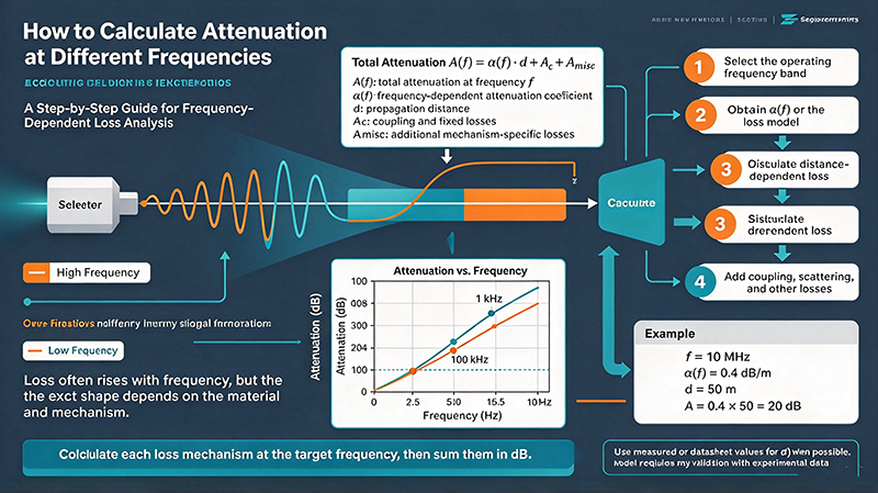
Cable attenuation increases with frequency because of two physical mechanisms: conductor loss from the skin effect (current is forced to flow in a thinner cross-section as frequency rises) and dielectric loss in the insulator between the conductors. Below a few GHz, conductor loss dominates and attenuation scales roughly with √f. Above a few GHz, dielectric loss grows linearly with f and eventually dominates.
The Attenuation Formula
Cable attenuation in dB/meter is well approximated by the formula:
α ≈ k₁·√f + k₂·f
where f is frequency in GHz, k₁ is the conductor-loss coefficient (depends on conductor material and cable geometry), and k₂ is the dielectric-loss coefficient (depends on the insulator's loss tangent and dielectric constant). The √f term dominates below a few GHz; the linear f term dominates at mmWave.
For polyethylene-dielectric coax at 1 GHz, k₁ is typically around 0.3–1 dB/m and k₂ is around 0.05–0.2 dB/m, depending on the cable size. Larger cables have smaller k₁ (lower conductor loss) but the same k₂ (the dielectric is the same).
Typical Cable Loss Numbers (dB per 10 m)
| Cable Type | 1 GHz | 6 GHz | 18 GHz | 40 GHz | Use Outside |
|---|---|---|---|---|---|
| RG-58 | 3.4 | 8.9 | — | — | Legacy test |
| RG-174 | 5.0 | 12.5 | — | — | Short jumpers |
| LMR-240 | 2.0 | 4.7 | — | — | Short flexible |
| LMR-400 | 0.9 | 2.3 | 4.7 | — | Tower-top to shelter |
| LMR-600 | 0.6 | 1.6 | 3.3 | — | Lower-loss runs |
| 0.141" semi-rigid | 0.7 | 2.0 | 3.8 | 6.2 | Lab test cables |
| 0.085" semi-rigid | 1.1 | 3.0 | 5.8 | 9.6 | Bench mmWave |
| 0.047" semi-rigid | 2.0 | 5.2 | 9.5 | 15.0 | On-wafer test |
Example Budget — 5 m LMR-400 at 10 GHz
A 5-meter LMR-400 run at 10 GHz loses about 1.2 dB. For a 1 dB-noise-figure LNA at the tower top, the receiver noise figure becomes roughly NF_total ≈ 1.2 + 0.8 = 2.0 dB — a noticeable penalty. For a 5G FR2 link at 28 GHz, the same cable loses 6–8 dB — half the transmitter power gone before it reaches the antenna.
The rule of thumb for receiver sensitivity: every 1 dB of cable loss before the LNA adds 1 dB to the system noise figure. Every 1 dB of cable loss after the PA reduces EIRP by 1 dB. Cable placement matters more than cable grade.
Why Larger Cable Is Lower Loss
Larger coaxial cable has lower loss because the surface area of the inner and outer conductors is greater, lowering the AC resistance per unit length. Doubling the cable diameter roughly halves the conductor loss — at the cost of weight, stiffness, and price. LMR-600 has about 1.5× the loss reduction of LMR-400 per dollar, but LMR-400 is more flexible and easier to install.
How Skin Effect Drives Conductor Loss
At DC, current flows uniformly through the entire cross-section of a conductor. At RF, the magnetic field inside the conductor creates eddy currents that push the current toward the surface. By 1 GHz, the effective conducting thickness is only about 2 µm in copper — the rest of the conductor carries no current. Because resistance is inversely proportional to cross-sectional area, the AC resistance rises as the skin depth decreases, which is why attenuation rises with √f.
Skin effect also explains why silver-plated conductors have measurably lower loss than bare copper at high frequencies — silver has a slightly higher conductivity than copper, and the plating ensures the current flows in the highest-conductivity material.
How to Reduce Cable Loss
Four practical techniques reduce cable loss in RF systems:
1. Use larger-diameter cable (LMR-600 instead of LMR-400). The loss reduction is roughly proportional to the inverse of the inner conductor diameter.
2. Move the LNA to the antenna. This eliminates cable loss before the LNA, which is the most damaging location for noise figure. DC power is delivered up the same coax using a bias tee.
3. Minimize cable length. Every meter counts. Route cables along the shortest practical path and avoid service loops.
4. Use phase-stable cable assemblies for test systems. Phase-stable cable uses a foamed dielectric that does not deform when bent, ensuring the cable's electrical length stays constant with flexure.
Other Cable Considerations
Power handling is also frequency-dependent. A cable rated for 1 kW CW at 1 MHz may only handle 100 W CW at 1 GHz. Attenuation converts forward power into heat inside the cable's dielectric, and that heat must be conducted away through the outer conductor and jacket.
Shielding effectiveness is another concern. Lower-quality cables leak RF energy, both radiating into the environment (causing EMC problems) and admitting external interference (degrading sensitivity). Double-shielded or tri-shielded cables are mandatory for many applications.
Frequently Asked Questions
Q: Does cable loss depend on the signal power? A: No. Cable attenuation is a property of the cable and the frequency. The signal power does not change the attenuation factor.
Q: How does temperature affect cable loss? A: Cable loss increases with temperature because conductor resistance rises. A cable that loses 3 dB at 25°C might lose 3.3 dB at 70°C.
Q: Can I repair a damaged cable? A: Yes for flexible coax using proper connectors, but the repair joint always has worse VSWR and slightly higher loss than the original. For precision test cables, factory repair is strongly preferred over field repair.
Engineering Notes from the Field
Cable selection for a new RF system is often the most expensive decision that no one bothers to budget. A 50-meter run of LMR-600 at 6 GHz loses about 8 dB. The same run of LMR-240 loses 23 dB — almost 90% of the signal gone. The cost difference between the two cables over 50 meters is roughly $300, which is far less than the cost of a low-noise amplifier that would compensate for the loss of the cheaper cable. Always include cable loss in the link budget before selecting cable type.
For tower-top installations, weather sealing and UV resistance matter as much as electrical performance. Standard PVC-jacketed cables degrade in direct sunlight within 5 years; polyethylene or fluoropolymer jackets last 20+ years. Water ingress is the most insidious failure mode — once water gets into a cable's dielectric, it cannot be removed, and the cable's loss increases by 1–3 dB depending on the volume of water.
Case Study: Cell Tower Cable Audit
A cellular carrier audited the cables on 200 cell towers and found that 15% of LMR-400 jumpers had been replaced within 5 years due to water ingress or UV damage. The replacement cost was $200 per jumper plus tower climb time. Switching to a higher-grade cable with a polyethylene jacket and flooded center conductor (waterproof gel that fills any cracks) reduced failure rate to under 2% over the same period, saving the carrier $400k annually. The lesson: cable selection has long-term operational costs that often exceed the upfront purchase price.
Closing Thoughts
Cable loss is one of the few RF engineering quantities that is fixed by physical reality and does not improve with clever design. You can design a perfect amplifier, but you cannot design a perfect cable. Choose the right cable for the job, install it carefully, and protect it from the environment. The savings will compound over the lifetime of the system.
Industry Applications and Use Cases
Across telecommunications, aerospace, defense, medical imaging, and automotive radar, the concepts covered in this guide show up in every RF design. From 5G base stations deploying massive MIMO antenna arrays with dozens of Wilkinson dividers per panel, to satellite payloads where every decibel of link budget determines the success of a multi-million-dollar mission, the principles remain the same: measure carefully, design with margin, and verify with the right instrument.
Medical applications add another wrinkle: MRI machines operate at the Larmor frequency of hydrogen (42.58 MHz/Tesla) and require extraordinarily low noise and high stability. Test systems for MRI receivers must minimize cable loss between the imaging coil and the low-noise preamplifier — often mounted directly on the coil housing — because every dB of loss degrades diagnostic image quality. The same matching, cabling, and LNA placement principles apply.
Automotive radar at 77 GHz is one of the fastest-growing RF domains. Each modern car may contain 5–10 mmWave radar units for adaptive cruise control, blind-spot detection, and automated emergency braking. These radar modules contain calibrated Wilkinson dividers, matched patch antennas, beam-steering phase shifters, and integrated FMCW synthesizers — all built on low-cost PCB substrates and tested in production at volumes exceeding 100 million per year. The principles taught in this guide are what make that volume manufacturing possible.
Advanced Design Considerations
Beyond the basics covered above, several advanced topics deserve attention as your designs mature. Multi-physics simulation — coupling electromagnetic, mechanical, and thermal effects in a single simulation — is increasingly important at mmWave frequencies where small dimensional changes from thermal expansion can shift the operating frequency. Tools like ANSYS HFSS, CST Studio Suite, and Cadence Clarity now include multi-physics capabilities that integrate structural and thermal solvers with the RF simulator.
Machine learning is beginning to appear in RF design. Surrogate models trained on simulation data can predict S-parameters 1000× faster than running the full EM simulation, enabling design space exploration that was previously impossible. Tools like Google Brain's RF antenna design work and Cadence's Cerebrus are early examples of where the field is heading. For now, these tools augment rather than replace the engineer's judgment — they accelerate iteration but the final design still needs to be understood, verified, and signed off by an experienced engineer.
Standards, Compliance, and Regulation
Every RF system must comply with applicable regulatory standards. In the United States, Part 15 of the FCC rules governs intentional radiators and unintentional emissions. The European Union's Radio Equipment Directive (RED) does similar work. Specific applications have additional standards: ETSI EN 301 893 for 5 GHz Wi-Fi, ETSI EN 302 500 for UWB, and many others. Military and aerospace applications have additional standards: MIL-STD-461 for EMI, MIL-STD-810 for environmental, and MIL-STD-1540 for product assurance.
Compliance testing is a discipline of its own. Compliance test labs use specialized instruments (spectrum analyzers with quasi-peak detectors, EMI receivers calibrated to CISPR standards) and follow specific procedures. The measurement uncertainty of compliance tests is typically ±3 to ±6 dB — much wider than production test measurements, but required for regulatory acceptance. Plan for compliance testing early in your design cycle; retrofitting a product to meet EMI requirements after the design is finalized is expensive and time-consuming.
Career and Skill Development in RF Engineering
RF engineering is a deep specialty with strong demand and excellent compensation. The barrier to entry is high: unlike software, you cannot iterate in seconds, and the cost of mistakes is paid in physical hardware. Yet for engineers who take the time to develop intuition, RF offers some of the most satisfying engineering work available — every component choice has a measurable effect, and every measurement reveals something about the physical world.
For those starting out, build a home lab. Even a modest setup with a cheap SDR (RTL-SDR, HackRF, or Airspy), a few antennas, and some cables will let you explore the RF spectrum in ways that no simulator can. Add a low-end spectrum analyzer (Rigexpert, TinySA) when you can afford it, and a used VNA from eBay when the budget allows. The hands-on experience with real signals, real cables, and real instruments is what builds intuition that no textbook can provide.
Stay current by reading industry publications (Microwave Journal, RF Globalnet, Microwaves & RF), attending conferences (IMS, EuMW, IEEE MTT-S), and joining professional communities (IEEE MTT-S, ACM SIGCOMM for networking RF). The field evolves rapidly — mmWave 5G, satellite internet, and automotive radar were niche markets 10 years ago and are now mainstream. The engineers who built those markets started by mastering exactly the fundamentals covered in this article.
About the Author — MeiXun Team
Chief Engineer Wang
High-tech Enterprise, Feifeng Talent
Chief Engineer Wang graduated with a master's degree in high-power microwave from the Institute of Electronics, University of Chinese Academy of Sciences.
View Full Profile- RF Switch Circuit Diagram
- RF Switch
- Ohm's Law
- dBm to Watt
- mW to dBm
- Wavelength to Frequency
- RF Connector
- SMA Connector
- RF Switch Module
- RF Coupler
- RF PIN Switch
- Microwave Coaxial Switch
- PIN Switch
- Coaxial RF Switch
- Waveguide Switch
- Microwave Switch
- Low Noise Amplifier
- PIN Diode Switch
- Coaxial Switch
- RF Microwave Switch
- SPST Switch