




























RF Cable Assembly Application Considerations
RF cable assemblies are the interconnects that carry high-frequency signals between antennas, amplifiers, filters, test instruments, and other RF components. A well-chosen cable assembly preserves signal integrity, maintains system calibration, and ensures long-term reliability. However, many engineers overlook critical application considerations that can lead to excessive loss, phase instability, EMI leakage, or mechanical failure.
This article covers the essential factors you must evaluate when selecting an RF cable assembly for your specific application, whether it is in a laboratory, a base station, a vehicle, or a space-constrained module.
1. Frequency Range and Cable Type
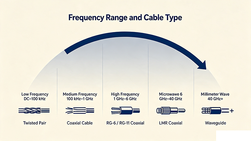
The operating frequency range dictates the type of coaxial cable you should choose. Different cable constructions are optimized for different bands. For example, semi-rigid cables offer excellent performance up to 40 GHz and beyond, while flexible cables like RG316 or LMR-100 are suitable for lower frequencies or applications requiring repeated flexure.
When selecting a cable assembly, verify that the cable's specified frequency range covers your entire signal band, including harmonics if they are present. At higher frequencies, insertion loss increases and phase stability becomes more challenging, so you may need a cable with a solid outer conductor or specialized dielectric.
2. Insertion Loss and Cable Length
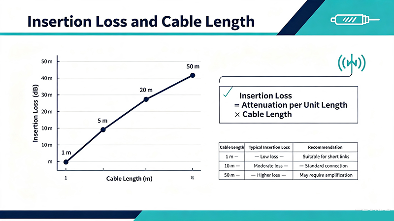
Insertion loss is the attenuation of signal power as it travels through the cable. It is directly proportional to cable length and increases with frequency. For long cable runs, even a low-loss cable can introduce significant attenuation. Always account for the total loss budget in your system.
As a rule of thumb, keep the cable as short as practically possible. If your application requires a longer run, select a cable with a larger diameter or a lower-loss dielectric. Also check the connector loss, which becomes significant at frequencies above 10 GHz.
3. VSWR and Return Loss
Voltage Standing Wave Ratio (VSWR) or return loss measures how well the cable assembly is matched to the system impedance (usually 50 Ω or 75 Ω). Poor VSWR causes reflections that can distort signals, reduce effective power transfer, and create measurement errors.
Look for cable assemblies with a VSWR of 1.20:1 or better (return loss ≥ 20 dB) across the operating band. Connector quality, cable-to-connector transition, and assembly workmanship significantly affect VSWR. Always specify a maximum VSWR requirement from your supplier.
4. Shielding Effectiveness
Shielding effectiveness determines how well the cable prevents external electromagnetic interference (EMI) from coupling into the signal path and also how much signal leaks out. In dense RF environments, poor shielding can cause cross-talk, spurious signals, and regulatory compliance issues.
High-quality RF cable assemblies use braided shields, foil shields, or a combination of both. For critical applications, consider double-shielded or solid-shield cables. Semi-rigid and conformable cables generally offer superior shielding compared to flexible braided cables.
5. Phase Stability and Temperature Effects
Phase stability is crucial in phased-array systems, radar, and vector measurement applications. As temperature changes or the cable flexes, the electrical length can vary, causing phase errors. Phase-stable cables use special dielectrics and construction techniques to minimize these changes.
If your application requires precise phase matching, specify a cable with a documented phase stability specification (e.g., ±0.05° per °C or less). For flexing applications, look for "flexure phase stable" cables that maintain performance under repeated bending.
6. Mechanical Stress and Bending Radius
Every cable has a minimum bend radius that should not be exceeded during installation or operation. Exceeding the bend radius can damage the dielectric, cause impedance discontinuities, and lead to premature failure. Static bend radius is the minimum for fixed installations, while dynamic bend radius is for applications with repeated flexing.
Always route cables with adequate slack and avoid sharp bends near connectors. Use cable ties or clamps that do not compress the cable excessively. For applications with continuous motion, choose a highly flexible cable designed for millions of flex cycles.
7. Environmental Considerations
RF cable assemblies may need to withstand moisture, chemicals, UV radiation, extreme temperatures, and altitude changes. Outdoor installations require weatherproof connectors and cable jackets that resist UV and water ingress. In aerospace or military applications, the cable must meet specific environmental standards.
Check the cable jacket material: PVC is common for indoor use, while FEP, PTFE, or polyurethane jackets offer better chemical and temperature resistance. Hermetically sealed connectors may be required for high-reliability applications.
8. Connector Type and Mating Compatibility
The connector type must match your equipment interfaces and maintain performance at the operating frequency. Common RF connectors include SMA, N, BNC, TNC, 2.92 mm (K), 2.4 mm, and 1.85 mm (V). Each has a defined upper frequency limit and power handling capability.
Also pay attention to connector gender and polarity. Ensure that the mating connectors are compatible and that the connection is properly torqued. Loose connections can cause intermittent faults and damage at high power levels.
9. Power Handling Capability
Power handling is determined by the cable's dielectric and inner conductor diameter, as well as the connector's construction. Exceeding the power rating can cause overheating, dielectric breakdown, and connector arcing. Always specify the maximum average and peak power your application will experience.
For high-power applications, use larger diameter cables like LMR-400 or hardline, and select connectors rated for high power (e.g., N or 7/16 DIN). Derate power handling at elevated temperatures and at higher frequencies.
10. Cost, Weight, and Maintainability
While performance is critical, cost and weight are also important. Semi-rigid cables offer excellent performance but may be more expensive and difficult to route. Flexible cables are easier to install but may have higher loss. Consider the total life-cycle cost, including installation time, replacement frequency, and maintenance accessibility.
In space-constrained designs, low-profile connectors and smaller diameter cables can save valuable real estate. In field-deployable systems, quick-disconnect connectors and ruggedized jackets may reduce downtime.
Quick Reference: RF Cable Assembly Selection Parameters
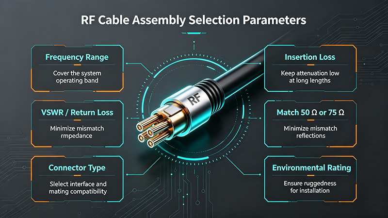
| Consideration | Typical Requirement | Impact if Ignored |
|---|---|---|
| Frequency Range | Covers full operating band | Excessive loss, phase distortion |
| Insertion Loss | Meets system loss budget | Reduced signal-to-noise ratio |
| VSWR / Return Loss | ≤ 1.20:1 (≥ 20 dB) | Reflections, signal ripple |
| Shielding Effectiveness | > 90 dB at operating band | EMI leakage, cross-talk |
| Minimum Bend Radius | Not exceeded during install/use | Dielectric damage, failure |
| Temperature Range | -55°C to +125°C typical | Phase drift, jacket cracking |
| Connector Type | Matches equipment, torque spec | Intermittent contact, damage |
| Power Handling | 1.5x to 2x max power | Overheating, arcing |
- Frequency range fully covers the signal band
- Insertion loss budget includes cable length and connectors
- VSWR meets system matching requirements
- Shielding effectiveness is adequate for EMI environment
- Phase stability requirements documented for temperature/flexure
- Bend radius will not be exceeded during installation or operation
- Environmental sealing and jacket material suit the location
- Connector type, gender, and torque specifications are correct
- Power handling capability exceeds worst-case operating power
- Cost and weight fit within project constraints
Conclusion
Selecting the right RF cable assembly requires a holistic view of electrical, mechanical, and environmental factors. A cable that meets the frequency and loss specifications but fails under mechanical stress or extreme temperatures will compromise the entire system. By carefully evaluating the application considerations outlined above, you can choose a cable assembly that delivers reliable performance, minimizes signal degradation, and extends the service life of your RF system.
Always work closely with your cable assembly vendor to define your specific requirements and request comprehensive test data before finalizing your selection.
About the Author — MeiXun Team
Chief Engineer Wang
High-tech Enterprise, Feifeng Talent
Chief Engineer Wang graduated with a master's degree in high-power microwave from the Institute of Electronics, University of Chinese Academy of Sciences.
View Full Profile- RF Switch Circuit Diagram
- RF Switch
- Ohm's Law
- dBm to Watt
- mW to dBm
- Wavelength to Frequency
- RF Connector
- SMA Connector
- RF Switch Module
- RF Coupler
- RF PIN Switch
- Microwave Coaxial Switch
- PIN Switch
- Coaxial RF Switch
- Waveguide Switch
- Microwave Switch
- Low Noise Amplifier
- PIN Diode Switch
- Coaxial Switch
- RF Microwave Switch
- SPST Switch