Coaxial adapters and
waveguide-coaxial adapters are both used to connect
RF and microwave components, but they solve different interconnection problems. A coaxial adapter changes one coaxial connector interface to another, while a waveguide-coaxial adapter converts between a coaxial transmission line and a
waveguide. Understanding the differences is essential when designing high-frequency systems, laboratory test setups, radar front ends, antennas, and microwave communication equipment.
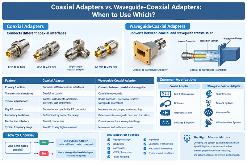
The right adapter can have a major impact on insertion loss, return loss, VSWR, power handling, frequency range, and overall system reliability. Choosing an adapter based only on connector appearance or mechanical compatibility can lead to significant RF performance degradation.
This guide explains the differences between coaxial adapters and waveguide-coaxial adapters, how each type works, where they are commonly used, and which factors RF engineers should consider when selecting an adapter.
What Is a Coaxial Adapter?

A coaxial adapter is an RF component used to connect two coaxial interfaces that have different connector types, genders, or mechanical configurations. The adapter maintains a controlled RF transmission path between the connected coaxial components.
Common coaxial connector interfaces include SMA, 2.92 mm, 2.4 mm, 1.85 mm, N-type, TNC, BNC, and other specialized RF connectors. For example, an SMA-to-N adapter allows equipment with an SMA interface to connect to equipment using an N-type interface.
Typical Coaxial Adapter Configurations
-
SMA male to SMA female
-
SMA to N-type
-
SMA to 2.92 mm
-
2.4 mm to 2.92 mm
-
1.85 mm to 2.92 mm
-
Male-to-male and female-to-female configurations
-
Right-angle coaxial adapters
-
Precision laboratory-grade coaxial adapters
The primary purpose of a coaxial adapter is therefore interface conversion within the coaxial domain.
What Is a Waveguide-Coaxial Adapter?

A waveguide-coaxial adapter, also called a coaxial-to-waveguide adapter or waveguide-to-coax adapter, connects a coaxial transmission line to a rectangular or circular waveguide.
Unlike a conventional coaxial adapter, it does not simply change one connector into another. It performs an electromagnetic transition between two fundamentally different transmission structures.
Coaxial cables transmit electromagnetic energy through a structure consisting of a center conductor, dielectric material, and outer conductor. Waveguides, by contrast, guide electromagnetic energy through a hollow metallic structure. Because their propagation mechanisms are different, the transition must be carefully engineered to provide efficient energy transfer.
Typical Waveguide-Coaxial Adapter Structure
A typical waveguide-coaxial adapter contains a coaxial connector or coaxial port, a transition section, and a waveguide flange. The transition geometry is designed to excite the desired waveguide mode while minimizing reflections and unwanted modes.
In rectangular waveguide systems, the dominant mode is commonly the TE10 mode. The transition structure must therefore be designed so that energy from the coaxial input couples efficiently into the appropriate waveguide mode.
Coaxial Adapters vs. Waveguide-Coaxial Adapters
|
Characteristic
|
Coaxial Adapter
|
Waveguide-Coaxial Adapter
|
|
Primary function
|
Connects different coaxial interfaces
|
Converts between coaxial and waveguide transmission
|
|
Transmission structures
|
Coaxial to coaxial
|
Coaxial to waveguide
|
|
Typical applications
|
RF cables, instruments, amplifiers, switches, test equipment
|
Radar, antennas, microwave systems, waveguide assemblies, high-frequency testing
|
|
Key RF concern
|
Connector compatibility and RF continuity
|
Mode conversion, impedance matching, insertion loss and VSWR
|
|
Frequency limitation
|
Determined mainly by connector design
|
Determined by waveguide size, mode, transition and connector technology
|
|
Mechanical interface
|
Coaxial connectors
|
Coaxial connector plus waveguide flange
|
|
Typical frequency range
|
From low RF to very high microwave frequencies
|
Commonly used in microwave and millimeter-wave systems
|
How Does a Coaxial Adapter Work?
A coaxial adapter provides a continuous electrical path between two coaxial connectors. The adapter preserves the basic coaxial geometry while changing the mechanical interface.
For example, an SMA-to-2.92 mm adapter connects two connector standards while maintaining a controlled characteristic impedance, typically 50 ohms in RF and microwave systems.
At high frequencies, the internal geometry becomes increasingly important. Small discontinuities can introduce parasitic capacitance or inductance, increasing reflection and insertion loss.
Key point: A high-frequency coaxial adapter should not be selected only because the two connectors mechanically fit. The frequency rating, impedance, VSWR, insertion loss, connector precision, and power handling capability must also match the application.
How Does a Waveguide-Coaxial Adapter Work?
A waveguide-coaxial adapter performs an electromagnetic transition from a coaxial transmission line to a waveguide. The transition is designed to couple energy from the coaxial center conductor into the appropriate electromagnetic field distribution inside the waveguide.
This process is more complex than changing between two coaxial connector types because the adapter must control the electromagnetic field distribution and waveguide mode.
The design of the probe, backshort, transition geometry, waveguide dimensions, and flange interface can all influence RF performance.
Important Waveguide Parameters
-
Waveguide band
-
Waveguide internal dimensions
-
Cutoff frequency
-
Operating frequency range
-
Dominant mode
-
Insertion loss
-
Return loss
-
VSWR
-
Power handling capability
-
Waveguide flange type
When Should You Use a Coaxial Adapter?
A coaxial adapter is normally the appropriate choice when both sides of the connection use coaxial transmission lines but the connector interfaces are different.
1. Connecting Different RF Connector Types
If a vector network analyzer has a 2.92 mm port while the device under test uses an SMA connector, an appropriate coaxial adapter can provide the required interface conversion.
2. RF Laboratory Test Equipment
Coaxial adapters are widely used in RF laboratories to connect signal generators, spectrum analyzers, VNAs, power meters, attenuators, amplifiers, filters, and RF switches.
3. RF Cable Assembly Integration
Different RF cable assemblies may use different connector standards. Coaxial adapters allow these assemblies to be integrated without redesigning the entire cable system.
4. High-Frequency Connector Conversion
Precision coaxial adapters are particularly useful in millimeter-wave test systems where connector families such as 1.85 mm, 2.4 mm, and 2.92 mm are commonly encountered.
When Should You Use a Waveguide-Coaxial Adapter?
A waveguide-coaxial adapter is appropriate when one part of the RF system uses coaxial transmission and another part uses waveguide.
1. Radar Systems
Radar equipment frequently combines coaxial electronics with waveguide antenna and RF front-end structures. A waveguide-coaxial transition can connect amplifiers, switches, receivers, or test equipment to a waveguide subsystem.
2. Microwave Antenna Systems
Many microwave antennas use waveguide interfaces because waveguide can provide low-loss transmission and high power handling at suitable frequencies. A coaxial-to-waveguide adapter provides the transition between coaxial equipment and the antenna feed.
3. Microwave Test and Measurement
Waveguide components such as filters, directional couplers, loads, antennas, and switches may need to be tested using coaxial instruments. A waveguide-coaxial adapter provides the interface required for the measurement setup.
4. Millimeter-Wave Systems
As operating frequencies increase, waveguide becomes increasingly important in many microwave and millimeter-wave systems. Waveguide-coaxial transitions can therefore be used to connect precision coaxial interfaces to waveguide components.
Frequency Range: A Critical Selection Factor
Frequency is one of the most important parameters when selecting either type of RF adapter.
For coaxial adapters, the connector architecture determines much of the upper frequency capability. For example, larger connectors such as N-type are commonly used at lower microwave frequencies than precision miniature connectors designed for millimeter-wave operation.
For waveguide-coaxial adapters, the operating range is strongly related to the waveguide band and physical dimensions. A waveguide has a cutoff frequency below which the desired mode cannot propagate normally.
Engineers should therefore verify that the adapter's specified frequency range covers the complete operating bandwidth rather than selecting an adapter based only on the nominal system frequency.
VSWR and Return Loss
VSWR and return loss are important indicators of how well an RF adapter matches the transmission system.
A poor impedance transition causes part of the incident RF signal to be reflected toward the source. Excessive reflection can reduce delivered power and introduce measurement errors.
In precision microwave applications, engineers should compare the adapter's specified VSWR or return loss across the complete operating frequency range.
Design tip: Do not evaluate RF adapters using a single VSWR value at one frequency. Broadband applications require performance data across the actual operating band.
Insertion Loss Considerations
Insertion loss represents the reduction in signal power caused by inserting a component into the RF path.
A coaxial adapter generally introduces relatively small additional loss when properly designed and operated within its specified frequency range. However, at microwave and millimeter-wave frequencies, connector geometry, surface finish, manufacturing tolerances, and assembly quality can have a noticeable effect.
Waveguide-coaxial adapters can introduce additional transition loss because the RF signal must change from one propagation structure to another. A high-quality transition is therefore important when system loss budgets are tight.
Impedance Matching
Most RF coaxial systems use a characteristic impedance of 50 ohms. The adapter should maintain the intended impedance throughout the transition.
Waveguide systems do not have a characteristic impedance in exactly the same sense as a conventional coaxial transmission line. Instead, their electromagnetic behavior is described through modal propagation and wave impedance.
This difference is one reason why a waveguide-coaxial transition requires more careful electromagnetic design than a simple coaxial connector adapter.
Power Handling
Power handling is another important selection criterion.
In high-power RF systems, excessive electric-field concentration can cause dielectric breakdown, arcing, heating, or other damage. Waveguide components can offer significant power-handling advantages at appropriate frequencies and operating conditions.
The actual power rating of an adapter depends on frequency, duty cycle, ambient conditions, connector construction, VSWR, cooling, and other factors. Engineers should always use the manufacturer's specified power rating rather than assuming that all adapters of the same connector type have identical capabilities.
Mechanical Compatibility Matters Too
RF performance is only one part of adapter selection. Mechanical compatibility is equally important for reliable system integration.
For coaxial adapters, verify connector gender, interface standard, mating mechanism, dimensions, and cable routing requirements.
For waveguide-coaxial adapters, additional parameters include waveguide flange type, flange dimensions, bolt-hole pattern, orientation, and alignment.
RF Adapter Selection Checklist
-
Confirm the required transmission-line type.
-
Confirm connector or waveguide interface compatibility.
-
Check the operating frequency range.
-
Verify characteristic impedance where applicable.
-
Compare insertion loss.
-
Check VSWR or return loss.
-
Verify power handling requirements.
-
Check connector gender and mechanical configuration.
-
For waveguide products, verify waveguide band and flange type.
-
Consider environmental requirements such as temperature, vibration, and humidity.
Common Applications Compared
|
Application
|
Recommended Interface
|
Reason
|
|
SMA equipment to N-type equipment
|
Coaxial adapter
|
Both systems use coaxial transmission
|
|
VNA to coaxial DUT
|
Coaxial adapter
|
Connector interface conversion
|
|
VNA to waveguide filter
|
Waveguide-coaxial adapter
|
Converts coaxial measurement port to waveguide
|
|
Coaxial amplifier to waveguide antenna
|
Waveguide-coaxial adapter
|
Connects different transmission structures
|
|
Radar waveguide assembly testing
|
Waveguide-coaxial adapter
|
Provides coaxial test equipment access
|
|
2.4 mm cable to 2.92 mm equipment
|
Coaxial adapter
|
Precision coaxial interface conversion
|
Common Mistakes When Selecting RF Adapters
Choosing Based Only on Connector Size
Two connectors may look mechanically similar but have significantly different frequency specifications and RF performance. Always check the electrical specifications.
Ignoring the Operating Bandwidth
An adapter rated for a narrow frequency range may not provide acceptable performance across a broadband application.
Ignoring VSWR
High VSWR can create reflections that affect sensitive RF measurements and system performance.
Using an Adapter Outside Its Power Rating
High RF power can cause excessive heating or electrical breakdown. Power handling should always be checked under the actual operating conditions.
Mixing Waveguide Standards
Waveguide components must be matched by waveguide band and flange standard. Mechanical compatibility alone does not guarantee correct electromagnetic performance.
How to Choose Between a Coaxial Adapter and a Waveguide-Coaxial Adapter
The selection process can be simplified by asking one fundamental question:
Are both sides of the connection coaxial?
If the answer is yes, a coaxial adapter is normally the appropriate solution.
If one side is coaxial and the other side is a waveguide, a waveguide-coaxial adapter is required.
After determining the interface type, engineers should evaluate frequency, bandwidth, insertion loss, VSWR, power handling, impedance, connector or flange configuration, environmental conditions, and dimensional requirements.
Frequently Asked Questions
What is the main difference between a coaxial adapter and a waveguide-coaxial adapter?
A coaxial adapter connects two coaxial interfaces, while a waveguide-coaxial adapter converts between coaxial transmission and waveguide transmission.
Can a coaxial adapter connect directly to a waveguide?
A conventional coaxial connector adapter is not a substitute for a properly designed waveguide-coaxial transition. A dedicated waveguide-coaxial adapter is normally required.
Why are waveguide-coaxial adapters used at high frequencies?
Waveguide technology can provide low-loss transmission and high power-handling capability in suitable microwave and millimeter-wave frequency bands. A waveguide-coaxial adapter allows coaxial equipment to interface with these systems.
What parameters should I check when buying a waveguide-coaxial adapter?
Important parameters include frequency range, waveguide band, flange type, connector type, insertion loss, return loss, VSWR, power handling, mechanical dimensions, and environmental specifications.
Are coaxial adapters suitable for millimeter-wave applications?
Yes. Precision coaxial connector systems such as 2.92 mm, 2.4 mm, and 1.85 mm are designed for high-frequency applications. The actual usable frequency depends on the specific connector and adapter design.
Conclusion
Coaxial adapters and waveguide-coaxial adapters serve different RF interconnection requirements. A coaxial adapter is primarily used to connect different coaxial connector interfaces, making it useful for RF cables, test equipment, amplifiers, switches, filters, and other coaxial components.
A waveguide-coaxial adapter is designed for a more fundamental transmission-line transition between coaxial and waveguide structures. It is commonly used in radar, microwave communication, antenna systems, high-frequency test setups, and millimeter-wave applications.
The correct choice should be based on the transmission structure first, followed by frequency range, bandwidth, VSWR, insertion loss, power handling, mechanical interface, waveguide band, and environmental requirements. Selecting the right adapter can help maintain signal integrity and achieve reliable RF system performance.
Related RF topics: Coaxial Connectors, Waveguide Adapters, Waveguide-to-Coaxial Adapters, RF Connectors, Microwave Components, RF Test and Measurement, Millimeter-Wave Components, Directional Couplers, RF Switches, and Microwave Antennas.


























