




























90 Degree Hybrid Couplers: Working Principles, Applications, and Design Essentials
In modern radio frequency (RF) and microwave engineering, precise signal manipulation is crucial for performance optimization. Among the most essential passive components used today is the 90 degree hybrid coupler, also commonly referred to as a quadrature hybrid coupler or 3 dB hybrid coupler. This component plays a vital role in splitting, combining, and routing RF signals while maintaining a constant phase relationship.
Whether you are designing advanced radar systems, 5G wireless base stations, or high-power RF amplifiers, understanding how a 90 degree hybrid coupler operates can significantly enhance system efficiency and isolation.
Key Takeaway: A 90 degree hybrid coupler is a 4-port directional coupler that splits an input power equally between two output ports with a 90-degree phase difference, while providing high isolation to the fourth port.
What is a 90 Degree Hybrid Coupler?
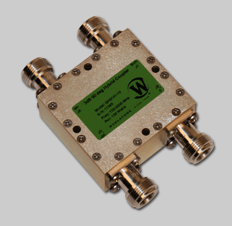
A 90 degree hybrid coupler is a four-port passive RF device designed to divide an incoming signal into two equal-amplitude outputs that are $90^\circ$ out of phase with each other. Conversely, it can also be used to combine two signals with appropriate phase relationships into a single output.
The standard four ports of a quadrature hybrid coupler are defined as follows:
- Port 1 (Input Port): The signal enters through this port.
- Port 2 (Direct/Through Port): Receives half of the input power ($3\text{ dB}$ down) with $0^\circ$ relative phase shift.
- Port 3 (Coupled Port): Receives the remaining half of the input power ($3\text{ dB}$ down) with a $90^\circ$ relative phase shift.
- Port 4 (Isolated Port): Ideally receives zero power under matched load conditions, terminating unwanted reflections.
How Does a Quadrature Hybrid Coupler Work?
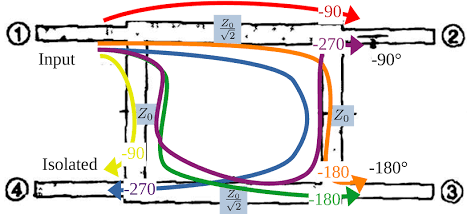
The fundamental operating mechanism of a 90 degree hybrid coupler relies on electromagnetic coupling across transmission lines, such as microstrip lines, striplines, or coaxial structures. When an RF signal enters Port 1, power divides evenly across the inner junction paths.
Because of the physical and electrical lengths of the coupling paths—typically quarter-wavelength ($\lambda/4$) transmission lines—the signal reaching the Coupled Port travels a path length that introduces an additional quarter-cycle delay relative to the Direct Port. This creates the characteristic $90^\circ$ phase offset between the two output signals.
| Input Port | Direct Port Output | Coupled Port Output | Isolated Port |
|---|---|---|---|
| Port 1 (0 dB @ 0°) | -3 dB @ 0° | -3 dB @ -90° | Fully Isolated (< -20 dB) |
| Port 2 (0 dB @ 0°) | -3 dB @ 0° | Fully Isolated | -3 dB @ -90° |
Key Performance Parameters
When selecting or designing a 90 degree hybrid coupler for your RF system, several critical specifications must be evaluated to ensure optimal network performance:
1. Coupling and Insertion Loss
A standard hybrid coupler delivers a nominal $3\text{ dB}$ split, meaning half the power goes to each output port. Theoretical insertion loss is $3\text{ dB}$, but physical conductor and dielectric losses typically add a small amount of extra loss (usually between $0.1\text{ dB}$ and $0.5\text{ dB}$).
2. Phase and Amplitude Balance
Phase balance refers to how accurately the device maintains the $90^\circ$ differential across its operating frequency band. Amplitude balance measures how evenly the power is divided between the direct and coupled ports. High-quality couplers maintain phase balance within $\pm 2^\circ$ to $\pm 5^\circ$.
3. Isolation
Isolation measures how much power leaks into the isolated port when a signal is applied to the input port. Higher isolation (typically $20\text{ dB}$ to $30\text{ dB}$ or better) ensures minimal crosstalk and protects sensitive driver stages.
4. Voltage Standing Wave Ratio (VSWR) / Return Loss
Good impedance matching across all four ports minimizes signal reflection. A low VSWR (typically less than $1.2:1$ or $1.3:1$) is essential for stable RF operation.
Common Types of 90 Degree Hybrid Couplers
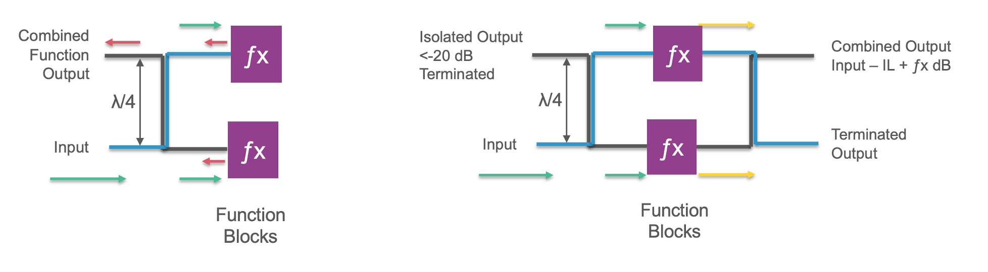
Depending on frequency range, power handling requirements, and form factor, different physical topologies are employed:
- Branch-Line Couplers: Built using planar microstrip or stripline quarter-wave sections. They offer simple design and low fabrication cost, ideal for narrow to moderate bandwidths.
- Lange Couplers: Utilize interdigital microstrip lines to achieve wide bandwidths (over an octave) in compact integrated circuits (MMICs).
- Coaxial and Air-Line Hybrids: Designed for high-power broadcast, radar, and aerospace applications demanding high power handling and ultra-low insertion loss.
- LTCC / Surface Mount Couplers: Small, surface-mount chip components optimized for high-volume commercial telecommunications and consumer electronics.
Main Applications of 90 Degree Hybrid Couplers
Due to their unique phase separation and isolation properties, quadrature hybrids are widespread across RF architecture:
1. Balanced Amplifiers
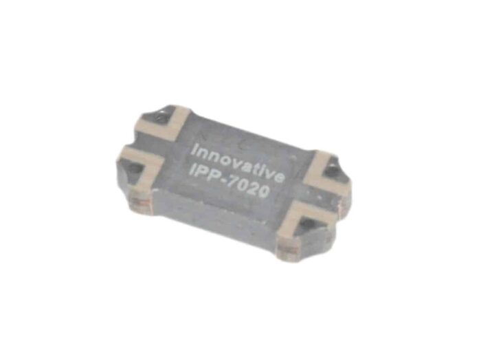
In a balanced power amplifier configuration, two identical amplifiers are placed between two 90 degree hybrid couplers. Reflections caused by impedance mismatches at the amplifier inputs travel back to the coupler and combine out of phase at the input port, cancelling each other out. The reflected energy dumps into the isolated port load, maintaining excellent input/output VSWR regardless of amplifier tuning.
2. Quadrature Modulators and Demodulators (I/Q)
Modern digital wireless communication relies heavily on In-phase (I) and Quadrature (Q) modulation schemes. A 90 degree hybrid splits a local oscillator (LO) signal into two orthogonal reference signals with a precise $90^\circ$ shift, enabling I/Q signal processing in 4G/5G receivers and transmitters.
3. Variable Phase Shifters and Attenuators
By connecting identical reflective components (such as PIN diodes or varactors) to the direct and coupled ports of a 90 degree hybrid, varying the diode bias alters the reflected phase or amplitude. The combined output exits through the isolated port, creating a voltage-controlled phase shifter or attenuator.
4. Antenna Beamforming Networks
In phased-array antenna systems, 90 degree hybrid couplers are combined into matrices (such as the Butler Matrix) to construct complex multi-beam steering networks without requiring active electronic phase shifters.
Summary
The 90 degree hybrid coupler remains a fundamental component in high-performance microwave and RF system design. By offering equal power division, high port-to-port isolation, and precise $90^\circ$ quadrature phase shifts, it enables stable power amplifiers, accurate digital modulation, and versatile signal combination across aerospace, defense, and telecommunication sectors.
About the Author — MeiXun Team
Chief Engineer Wang
High-tech Enterprise, Feifeng Talent
Chief Engineer Wang graduated with a master's degree in high-power microwave from the Institute of Electronics, University of Chinese Academy of Sciences.
View Full Profile- RF Switch Circuit Diagram
- RF Switch
- Ohm's Law
- dBm to Watt
- mW to dBm
- Wavelength to Frequency
- RF Connector
- SMA Connector
- RF Switch Module
- RF Coupler
- RF PIN Switch
- Microwave Coaxial Switch
- PIN Switch
- Coaxial RF Switch
- Waveguide Switch
- Microwave Switch
- Low Noise Amplifier
- PIN Diode Switch
- Coaxial Switch
- RF Microwave Switch
- SPST Switch