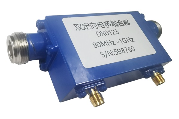
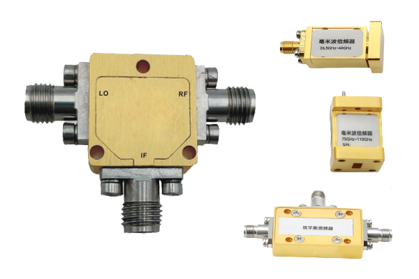
What is the core working principle of the Dual directional coupler
Dual Directional Coupler Technical Specification
1. Core Structure Composition
The Dual directional coupler is composed of a main transmission line, two sets of coupling lines and matching loads.
-
The main transmission line is responsible for the transmission of the main RF signal.
-
The two sets of coupling lines correspond to the forward and reverse transmission directions of the signal respectively.
-
The matching load is used to absorb excess energy and ensure the stability of signal transmission.
2. Forward Signal Coupling Process
⚡
When the RF signal propagates forward along the main transmission line, part of the energy will be captured by the forward coupling line through the electromagnetic induction effect.
-
These coupled signals will be guided to the corresponding output port to achieve sampling and monitoring of the forward transmission signal.
-
The signal of the main transmission line can still maintain stable transmission.
3. Reverse Signal Coupling Process
↩
If the RF signal is transmitted in the reverse direction along the main transmission line, the other set of reverse coupling lines will play a role.
-
Through the same electromagnetic induction principle, part of the signal energy transmitted in the reverse direction will be captured.
-
The reverse coupling line transmits to the corresponding output port, achieving effective monitoring of the reverse transmission signal.
4. Key Design Guarantee
Optimization of spatial layout, material selection and relative position ensures non-interference between forward and reverse coupling signals.
-
By optimizing the spatial layout, material selection and relative position of the coupling line and the main transmission line.
-
The matching load at the isolation end absorbs useless signals, avoiding reflection interference with the main signal.
-
Ensures the purity and measurement accuracy of the coupling signal for reliable signal sampling and power monitoring.


