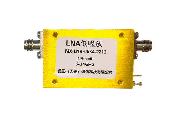
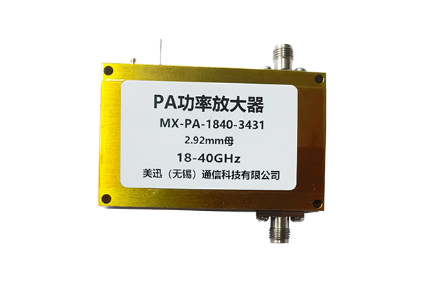
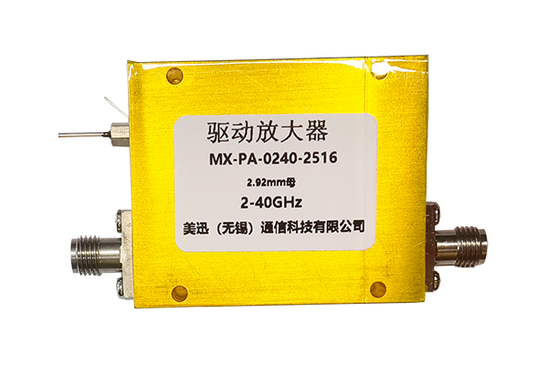
Performance indicators of low-noise amplifiers
The noise figure measures the degree of additional noise introduced by the amplifier during the amplification of the signal. It is the ratio of the input signal-to-noise ratio to the output signal-to-noise ratio, usually expressed in dB. A lower noise figure means that the amplifier itself generates less noise and can better preserve the original quality of the input signal. In RF and microwave communication systems, especially when amplifying weak signals, a low noise figure is crucial. For example, in the receiver front end of a satellite communication ground station, the ideal low-noise amplifier noise figure can be as low as 0.5-1dB.
2. Gain
The gain reflects the amplifier's ability to amplify the input signal, which is defined as the ratio of the output signal power to the input signal power, also in dB. Appropriate gain can amplify weak signals to a level that can be processed by subsequent circuits. However, the higher the gain, the better. Too high a gain may cause signal distortion and may also cause the amplifier to enter a saturated state, affecting system performance. The size of the gain needs to be reasonably designed and adjusted according to the specific application scenario.
3. Linearity
Linearity describes the amplifier's amplification consistency for signals of different amplitudes. Good linearity means that when the amplifier processes large and small signals, its gain remains relatively stable and does not produce significant distortion. The commonly used indicator for measuring linearity is the third-order intermodulation intercept point (IP3). The third-order intermodulation product is caused by the nonlinear characteristics of the amplifier and will interfere with the useful signal. A higher IP3 indicates that the amplifier has better linearity and can process signals with a larger dynamic range without severe distortion.
4. Bandwidth
Bandwidth refers to the frequency range in which the amplifier can effectively amplify the signal. Within this frequency range, the amplifier's performance indicators such as gain and noise figure meet the design requirements. Different application scenarios have different requirements for bandwidth. For example, in broadband communication systems, the amplifier needs to have a wider bandwidth to ensure that it can process signals in multiple frequency bands at the same time.
5. Input-output standing wave ratio (VSWR)
The input-output standing wave ratio reflects the matching degree between the input and output ports of the amplifier and the external circuit. A lower standing wave ratio means less reflection at the port, which can achieve more efficient power transmission. Generally speaking, the input-output standing wave ratio should be as close to 1 as possible to reduce the impact of signal reflection on system performance.


