




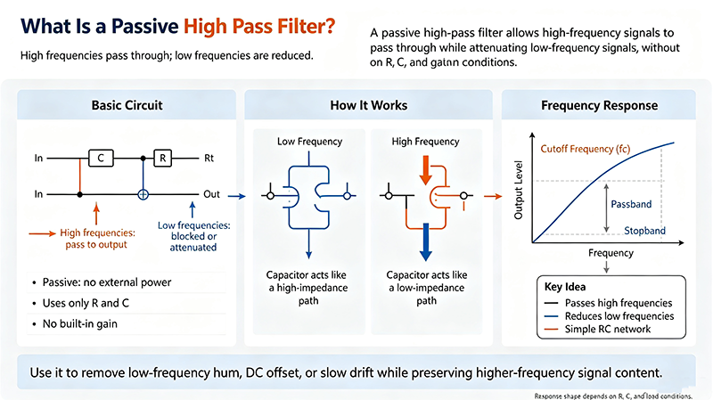
Learn what a passive high pass filter (HPF) is, how RC and RL circuits work, common topologies, cutoff frequency calculation, key specifications, applications, and design tips.
Sep 20 ,26


5G communication testing, wireless terminal automated testing
Aerospace communication systems
Precision measurement equipment, radio frequency signal control of radar transmitters
Communication and navigation systems
Optical communication module-related testing
Interconnection of wireless communication base stations
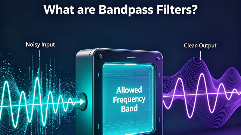
A passive band pass filter lets signals in a specific frequency range pass while rejecting everything below and above that range. Built from only resistors, capacitors, and inductors — no amplifiers, no power supply — it is the workhorse of RF, audio, and instrumentation design. This guide explains how it works, the common topologies, key specifications, where it shows up in real designs, and how to pick the right one for your application.
Quick answer: A passive band pass filter passes signals between a lower cutoff (fcL) and an upper cutoff (fcH) and rejects frequencies outside that band. A first-order LC BPF has a center frequency f0 = 1/(2π√LC) and a quality factor Q = f0/BW. Insertion loss is ≥ 0 dB at all frequencies.
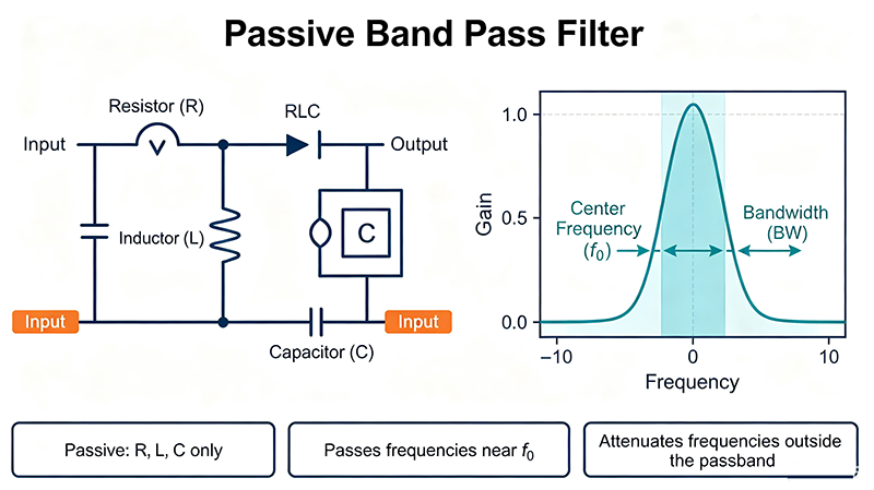
A passive band pass filter is a frequency-selective two-port network built from passive components only: resistors (R), capacitors (C), and inductors (L). It needs no power supply, contains no transistors or op-amps, and therefore can only attenuate — it can never provide gain.
Conceptually, a passive BPF is the cascade of a high-pass filter (which sets fcL) and a low-pass filter (which sets fcH). The result is a passband between fcL and fcH with two transition bands sloping off into the stopbands on either side.
Any reactive circuit has an impedance that varies with frequency. By combining series-LC and parallel-LC sections, you create a circuit that:
Every passive BPF is described by these fundamental parameters:
| Parameter | Symbol | Meaning | Typical Range |
|---|---|---|---|
| Center frequency | f0 | Midpoint of the passband | 1 kHz — 100 GHz |
| Lower cutoff (-3 dB) | fcL | Lower edge of passband | Set by HPF |
| Upper cutoff (-3 dB) | fcH | Upper edge of passband | Set by LPF |
| Bandwidth | BW | Width of passband (fcH - fcL) | Hz to MHz |
| Quality factor | Q | f0 / BW — selectivity | 1 — 10000+ |
| Insertion loss | IL | Loss at f0 (passive ≥ 0 dB) | 0.5 — 6 dB |
| Return loss | RL | Match at input/output | 10 — 20 dB |
| Stopband rejection | SB | Attenuation outside passband | 20 — 80+ dB |
| Shape factor | SF | Ratio of -60 dB BW to -3 dB BW | 1.5 : 1 — 5 : 1 |
| Group delay | τ | Phase linearity (data signals) | ns — μs |
| Power handling | Pmax | Maximum CW or peak input | mW — kW |
Series and parallel LC resonators cascaded. Most common general-purpose BPF.
Piezoelectric ceramic resonators. Excellent Q at HF/VHF, low cost.
Quartz crystal resonators. Very high Q, narrow bandwidth, used in IF stages.
Surface acoustic wave on piezoelectric substrate. Compact, used in RF front ends.
Bulk acoustic wave. Excellent Q at microwave frequencies, used in smartphones.
Resonant metal cavities. Highest Q at VHF/UHF, used in base stations.
Distributed transmission-line resonators. Used at GHz+ frequencies.
High-permittivity ceramic puck. Compact, high Q, microwave only.
| Topology | Frequency Range | Q | Bandwidth | Best For |
|---|---|---|---|---|
| LC ladder | DC — 1 GHz | 5 — 50 | 5 — 30% | General purpose, prototyping |
| Ceramic | 100 kHz — 100 MHz | 200 — 1000 | 1 — 10% | AM/FM IF, comms |
| Crystal | 1 — 200 MHz | 5000 — 50000 | 0.01 — 1% | SSB/CW IF stages |
| SAW | 30 MHz — 3 GHz | 100 — 2000 | 0.1 — 5% | Cellular front ends, GPS |
| BAW / FBAR | 1 — 10 GHz | 1000 — 5000 | 1 — 5% | Smartphone duplexers |
| Cavity | 30 MHz — 30 GHz | 2000 — 50000 | 0.1 — 2% | Cellular base stations, radar |
| Microstrip | 1 — 100 GHz | 100 — 1000 | 1 — 10% | Microwave subsystems |
| Response | Passband | Roll-off | Best For |
|---|---|---|---|
| Butterworth | Maximally flat | Moderate | General-purpose, when flatness matters |
| Chebyshev | Ripple allowed | Steeper | Sharpest transition at given order |
| Bessel | Flat amplitude | Gradual | Linear phase, pulse fidelity |
| Elliptic | Ripple in both bands | Steepest | Sharpest cutoff when ripple is OK |
| Gaussian | No overshoot | Smooth | Data and timing applications |
| Aspect | Passive BPF | Active BPF |
|---|---|---|
| Components | R, L, C only | Op-amp + R, C |
| Power supply | Not required | Required |
| Insertion loss | Always > 0 dB | Can be 0 dB or gain |
| Max frequency | Set by L/C parasitics | Limited by op-amp GBW |
| High-power RF | Excellent (no active devices) | Poor |
| Noise | Thermal only | Thermal + op-amp noise |
| Q achievable | Up to 50000 (cavity, crystal) | Usually < 100 |
| Cost | Low to moderate | Moderate |
A second-order LC circuit: a series LC resonator at the input followed by a parallel LC resonator to ground. Combined with the load resistor, it forms a single-pole pair (one section) band pass filter.
No. Passive components cannot add energy, so gain is always ≤ 0 dB. If you need gain, you must use an active topology or follow the passive filter with a separate LNA or PA.
It depends on your frequency and required Q. LC is best below 100 MHz with modest Q. Ceramic covers HF/VHF with higher Q. Crystal and SAW reach very high Q at RF, with SAW optimized for compact RF front ends.
Q is selectivity — the ratio of center frequency to bandwidth. A higher Q means a narrower, sharper passband at the same center frequency. Bandwidth is simply the width of the passband.
Real inductors have series resistance, real capacitors have parasitic resistance, and component Q is finite. Some signal energy is dissipated as heat in the filter — this is the insertion loss.
Yes. Cascading multiple filter sections produces a sharper roll-off (higher-order filter). The trade-off is higher cumulative insertion loss and greater sensitivity to component tolerances.
• A passive band pass filter passes a band of frequencies and rejects everything else, using only R, L, and C components.
• Center frequency is f0 = 1/(2π√LC), bandwidth is fcH - fcL, and selectivity is Q = f0/BW.
• Topologies range from LC ladders and ceramic resonators to SAW, BAW, crystal, cavity, and microstrip.
• Pick the topology that gives you the highest Q at your operating frequency.
• Passive BPFs dominate in RF, IF, audio, radar, SATCOM, and test equipment where no power supply and high Q matter most.
High-tech Enterprise, Feifeng Talent
Chief Engineer Wang graduated with a master's degree in high-power microwave from the Institute of Electronics, University of Chinese Academy of Sciences.
View Full Profile